


High-Voltage Test Transformers
High-voltage (HV) test transformers are dedicated devices designed to generate power-frequency high voltage, referred to as test transformers for short. Classified as step-up transformers, their core functions include insulation performance testing of electrical products, power-frequency withstand voltage testing, and partial discharge measurement, featuring a short-time operating characteristic.
Their operating voltage range covers 0.4 kV–10 kV on the primary side, and can reach 100–2000 kV or higher on the secondary side, with a capacity ranging from 3 kVA to 9000 kVA. The transformers adopt an oil-immersed self-cooled or SF₆ gas-insulated structure.
Categorized by structure, they are divided into iron-clad type, insulated-enclosure type, and single-bushing type; by power supply frequency, they include power-frequency type, frequency-multiplied type, etc.
The high-voltage winding adopts a multi-layer tower coil design, usually with one end grounded, while the low-voltage winding is externally mounted. Models with a capacity above 10 kVA are equipped with movable iron wheels, boasting the characteristics of compact size and light weight. The impedance voltage of a single unit ranges from 4.5% to 10%, and can reach 30% to 40% when multiple units are used in cascade. The output voltage waveform is nearly sinusoidal. The winding insulation materials use polyester enameled wire and high-voltage-resistant composite materials. The transformer body undergoes vacuum drying treatment, and vacuum oil filling is required for products with a voltage rating above 100 kV.
1. High-Voltage Test Transformers Classification by Structural Type
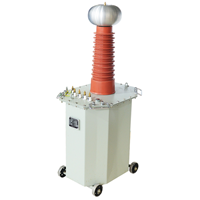
1.1 Oil-Immersed HV Test Transformers
As the most common type, the transformer body is immersed in insulating oil, which serves both as an insulation medium and a heat dissipation medium.
Advantages: Excellent insulation performance, large capacity, high voltage withstand level. Suitable for power-frequency withstand voltage testing, and widely used in power plants, substations, and high-voltage electrical equipment manufacturers.
Disadvantages: Large volume, heavy weight, relatively inconvenient for transportation and installation.
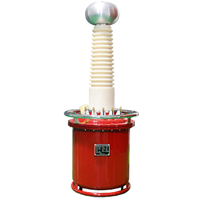
1.2 Dry-Type HV Test Transformers
Encapsulated by casting or winding solid insulation materials such as epoxy resin, they contain no insulating oil.
Advantages: Compact size, light weight, pollution-free, easy maintenance, strong resistance to humidity and contamination. Suitable for laboratory testing, indoor testing, or humid environments.
Disadvantages: Limited capacity and voltage rating compared with oil-immersed counterparts; slightly higher cost than oil-immersed products of the same specification.
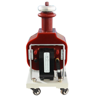
1.3 Gas-Insulated HV Test Transformers
Insulating gases such as sulfur hexafluoride (SF₆) or nitrogen are used as insulation and cooling media, sealed in a metal enclosure.
Advantages: High insulation strength, good heat dissipation effect, compact structure, no risk of oil leakage. Suitable for special environments such as high-altitude areas and explosion-proof sites.
Disadvantages: High requirements for gas sealing; regular gas pressure monitoring is needed during operation, leading to relatively high maintenance costs.
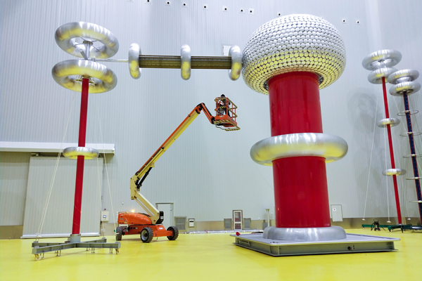
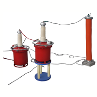
1.4 Cascade-Type HV Test Transformers
Composed of multiple single test transformers connected in series, ultra-high output voltage is achieved through step-by-step voltage boosting.
Advantages: Capable of generating ultra-high output voltage ranging from hundreds of thousands to millions of volts, meeting the testing requirements of ultra-high voltage equipment.
Disadvantages: Complex structure, high difficulty in voltage regulation and control, and stringent requirements for insulation and voltage equalization design.
| Oil-immersed High-voltage Test Transformer | Dry-type High-voltage Test Transformer | Gas-insulated High-voltage Test Transformer | Cascade-type High-voltage Test Transformer |
 |
 |
 |
 |
2. High-Voltage Test Transformers Classification by Voltage Regulation Mode
2.1 Autotransformer-regulated Test Transformers
Equipped with a built-in autotransformer, they adjust the input voltage by changing the number of turns in the primary winding, thereby varying the output high voltage.
Advantages: Simple structure, easy operation, and low cost. Suitable for test scenarios with small-to-medium capacity and low voltage levels.
2.2 Separately-regulated Test Transformers
The transformer body is separated from the voltage regulator, which usually adopts an electric voltage regulator or induction voltage regulator.
Advantages: High voltage regulation precision, stable output voltage, and support for remote control. Suitable for precision tests with large capacity and high voltage levels.
3. High-Voltage Test Transformers Classification by Test Waveform/Frequency
3.1 Power-frequency Test Transformers
They output 50Hz/60Hz sinusoidal alternating current and are used for power-frequency withstand voltage tests of electrical equipment. They are the most basic type of test transformers.
3.2 Variable-frequency Series Resonant Test Transformers
As resonant step-up equipment, they consist of a test transformer, excitation transformer, reactor, capacitor voltage divider, and other components to form a resonant circuit.
Advantages: Compact size, light weight, and high capacity utilization rate. Suitable for withstand voltage tests of capacitive test objects such as long cables, capacitors, and generators, and can effectively reduce the capacity demand of test equipment.
3.3 Impulse Test Transformers
Specially designed to generate lightning impulse voltage or switching impulse voltage, they simulate overvoltage surges in power systems.
Features: High instantaneous output voltage peak and short duration. They need to be used with an impulse voltage generator and are applied in impulse withstand voltage tests of equipment such as transformers and surge arresters.
3.4 Other Special Types
Portable High-voltage Test Transformers: Mostly dry-type or small oil-immersed type, they are compact, lightweight, and easy to move for on-site testing. Suitable for on-site detection of power lines and distribution equipment.
AC-DC Dual-purpose Test Transformers: Capable of outputting AC high voltage or DC high voltage, which can be switched via a rectifier device. One device serves multiple purposes, saving equipment investment.
High-Voltage Test Transformers Basic Introduction
Electrical equipment shall undergo AC withstand voltage tests after leaving the factory, handover, or major maintenance to assess the insulation level of the equipment against overvoltage in practice. Therefore, AC withstand voltage equipment shall be installed in high-voltage laboratories or test sites of both manufacturing and operation departments.
High-voltage test transformers are referred to as test transformers for short, which are generally step-up transformers. These test transformers utilize the power-frequency high voltage induced on their secondary side to conduct insulation performance tests on various electrical products and insulating materials.
Test transformers are indispensable electrical equipment for withstand voltage tests in the maintenance and manufacturing of motors, transformers, and electrical products.
The main applications of test transformers include power-frequency withstand voltage tests of electrical products, partial discharge measurement, thermal stability tests of insulating media, etc. For medium and high-frequency electrical equipment, test transformers with special frequencies can also be used for withstand voltage tests and measurement of relevant electrical parameters.
Test transformers have a large voltage ratio between primary and secondary windings. The primary voltage varies from 0.4kV, 3kV, 6kV to 10kV, while the secondary voltage can be designed to 100–2000kV or higher, with a capacity ranging from 3kVA to 9000kVA.
For on-site tests of power equipment, lightweight test transformers are generally used; 50kV step-up test transformers are applied for withstand voltage tests of power equipment such as 6kV and 10kV transformers; for withstand voltage tests of high-voltage and ultra-high-voltage power equipment with voltage levels above 35kV, ultra-high-voltage test transformers with a voltage more than 5 times the primary rated voltage of the tested equipment are adopted, such as 500kV, 700kV, 800kV step-up test transformers with specific capacity levels.
The working principle of test transformers is the same as that of power transformers. The differences are that test transformers feature high working voltage, short service time, and small temperature rise, and are generally not equipped with radiators. In addition, test transformers have small loads, mostly capacitive loads, and their capacity is relatively smaller than that of power transformers.
High-Voltage Test Transformers Features
High Voltage: The primary voltage of test transformers is 220V or 380V, while the secondary voltage of a single test transformer often reaches several thousand to tens of thousands of volts. Test transformers with a secondary voltage exceeding 750kV usually adopt a multi-unit cascade structure.
Low Current: The rated current of test transformers is actually the capacitive current of the test object, so it is generally less than 1A. However, test transformers used for cable and large motor tests, external insulation pollution tests, line corona tests and other projects can have a secondary current of several amps.
Short Working Time: Due to the short withstand voltage time of the tested products, test transformers adopt a short-time duty system of 0.5h or 1h in general, except for those used in external insulation pollution tests, line corona tests and cable tests.
Single-phase and Indoor Installation: Test transformers are generally single-phase and indoor devices (some are designed as outdoor devices). All adopt an oil-immersed self-cooled structure with thick winding insulation layers, and the high-voltage winding is usually grounded at one end.
Uneven Insulation Level of Secondary Winding: The head end of the secondary winding is at high potential, while the tail end is directly grounded or grounded through an ammeter.
High Design and Manufacturing Requirements: Due to the high working voltage, the insulation structure has a decisive impact on the overall size of the test transformer. The transformer body generally requires vacuum drying, and vacuum oil filling is required for products above 100kV.
High-Voltage Test Transformers Classification
By Structure: Iron-clad test transformers and insulated-enclosure test transformers.
By Power Frequency: Test transformers with frequency levels such as power frequency, frequency-multiplied, medium frequency and high frequency.
By Voltage Level: Low-voltage, high-voltage and ultra-high-voltage test transformers.
By Application Form: Lightweight mobile type and fixed type; test transformers for single-unit use and those for cascade use of two or more units.
Test transformers are generally single-phase, indoor devices with an oil-immersed self-cooled structure. Because of their high working voltage, their winding insulation layers are relatively thick, and one end of the high-voltage winding is grounded.
The specific structural types of test transformers generally include three types: single-bushing type, double-bushing type and insulating cylinder type.
High-Voltage Test Transformers Technical Requirements
Output Voltage Waveform: The output voltage waveform of test transformers should be as close to a sine wave as possible. To reduce voltage waveform distortion caused by harmonic voltage generated when the harmonic components of no-load current pass through the impedance of the voltage regulator and transformer, the magnetic flux density should be selected in the linear segment of the iron core magnetization curve. Meanwhile, voltage regulation equipment with small waveform distortion should be adopted, and filter devices can be added if necessary.
Impedance Voltage: The secondary current of test transformers is generally capacitive current. When the secondary current flows through the impedance of the voltage regulator and test transformer, the output voltage will exceed the value determined by the voltage ratio. Therefore, the impedance voltage of test transformers should not be too high, otherwise it may affect the accuracy of test results and reduce the short-circuit capacity of the test equipment. However, if the impedance voltage is too low, the short-circuit current may increase when the test object breaks down or flashes over. The impedance voltage of a single test transformer is generally 4.5~10%, and can reach 30~40% when multiple units are cascaded.
If you need to check the high voltage testing equipments and hv testing transformers. Please feel free to contact us. Our sales engineers are familiar with the Laboratory and indoor testing, low-to-medium voltage testing in humid/clean environments, power-frequency withstand voltage testing in power plants, substations and high-voltage electrical equipment factories, withstand voltage testing of ultra-high voltage equipment such as transformers and circuit breakers, precision testing for large-capacity and high-voltage-grade applications, impulse withstand voltage testing of equipment such as transformers and surge arresters, and on-site detection of power lines and distribution equipment.