


Research on Testing Technology and Equipment for Medium and High Voltage Transformers and Their Practical Significance
summary
As core power equipment in the power generation, transmission, transformation, and distribution links of a power system, the operational reliability of medium- and high-voltage transformers directly determines the safety, stability, power supply quality, and economic operation level of the power system. With the rapid development of my country’s power industry towards higher voltage, larger capacity, and intelligent operation, the application scenarios of medium- and high-voltage transformers (3.6kV~1000kV) are becoming increasingly widespread, and their operating environment is becoming increasingly complex. Various potential faults, such as winding aging, core damage, insulation deterioration, and partial discharge, occur frequently, seriously threatening the safe and stable operation of the power system and even causing large-scale power outages, resulting in huge economic losses and social impacts. Therefore, establishing a scientific and comprehensive medium- and high-voltage transformer testing system, employing precise and efficient testing technologies and equipment, and conducting comprehensive, full-lifecycle testing of transformers to promptly identify potential faults, assess equipment operating status, and diagnose fault types and causes, has become a crucial link in ensuring the safe and stable operation of the power system.
This paper focuses on the testing of medium- and high-voltage transformers. First, it defines the voltage range, structural composition, and working principle of medium- and high-voltage transformers, systematically analyzes common fault types and their mechanisms, and clarifies the core value of testing in the full life-cycle management of transformers. Second, it outlines the classification and core principles of the medium- and high-voltage transformer testing system, and provides a detailed interpretation of relevant national standards, offering a theoretical basis for the standardized implementation of testing work. Third, it elaborates on the testing principles, objectives, equipment used (including equipment structure, working principle, technical parameters, and model examples), and testing procedures for various testing items of medium- and high-voltage transformers (winding testing, core testing, insulation testing, insulating oil testing, partial discharge testing, withstand voltage testing, lightning impulse testing, etc.), deeply analyzing the practical significance and specific applications of each testing item and clarifying the compatibility requirements of testing equipment for different specifications of medium- and high-voltage transformers. Then, it verifies the effectiveness of various testing technologies and equipment in practical applications through engineering examples, further highlighting the importance of testing work. Finally, it discusses the development trend of medium- and high-voltage transformer testing technology, providing a reference for future upgrades and applications of testing technology. This paper, through a comprehensive and systematic study, aims to provide theoretical support and practical guidance for the standardization and precision of medium and high voltage transformer testing, promote the advancement of power system testing technology, ensure the safe and stable operation of medium and high voltage transformers, and contribute to the high-quality development of the power industry.
Keywords: medium and high voltage transformers; testing technology; testing equipment; fault diagnosis; operational reliability; significance of testing
Chapter 1 Introduction
1.1 Research Background and Significance
1.1.1 Research Background
The power industry is a pillar industry of the national economy, and the safe and stable operation of the power system is the foundation for ensuring the normal operation of industrial production, residents’ lives, and various social undertakings. Medium and high voltage transformers, as core equipment for energy conversion and transmission in the power system, undertake the important task of stepping up the electrical energy output from generators to high voltage for long-distance transmission, and then stepping it down to medium and low voltage for user use. They are widely used in power plants, substations, transmission lines, industrial enterprises, and other scenarios. With the advancement of my country’s “dual-carbon” goals, the large-scale grid connection of new energy sources (wind power, photovoltaic, nuclear power, etc.), and the rapid construction of ultra-high voltage transmission projects, the capacity of medium and high voltage transformers is constantly increasing, the voltage levels are continuously rising, and the operating conditions are becoming increasingly complex, facing the challenges of high temperature, high voltage, high load, and strong electromagnetic interference.
Medium and high voltage transformers have complex structures and precise manufacturing processes. They are mainly composed of core components such as windings, cores, insulation systems, insulating oil, bushings, and tap changers. During long-term operation, these components are subject to the combined effects of electric fields, magnetic fields, temperature, mechanical stress, and environmental factors (humidity, dust, corrosive gases, etc.), making them prone to aging, wear, damage, and deterioration, leading to various faults. Statistics show that the fault rate of medium and high voltage transformers in my country’s power system is increasing year by year, with insulation faults, winding faults, core faults, and insulating oil deterioration faults accounting for over 80%. For example, aging and damage to winding insulation can lead to short circuits and transformer burnout; multiple grounding points in the core can cause localized overheating, shortening the transformer’s service life; deteriorated insulating oil reduces the transformer’s insulation performance and cooling effect, inducing insulation breakdown faults; and persistent partial discharge accelerates insulation aging, ultimately leading to insulation failure and causing major power outages.
In recent years, large-scale power outages caused by medium- and high-voltage transformer failures have occurred frequently both domestically and internationally. In 2021, a short-circuit fault occurred in a main transformer at a 220kV substation in a certain region due to aging winding insulation, causing a complete power outage at the substation and affecting the normal power supply of several surrounding industrial enterprises and residential communities, resulting in direct economic losses exceeding ten million yuan. In 2022, a 330kV main transformer at a power plant experienced localized overheating due to multiple grounding points in its core, forcing the transformer to be shut down for maintenance, affecting the power plant’s generating efficiency and causing a significant power supply shortage. These accidents clearly demonstrate that failures in medium- and high-voltage transformers not only damage the equipment itself but also affect the reliability of the power supply system, causing enormous economic losses and social impacts.
Therefore, how to promptly identify potential faults in medium and high voltage transformers, assess their operating status, diagnose fault types and causes, and take targeted maintenance and repair measures to prevent fault expansion, extend transformer service life, and ensure the safe and stable operation of the power system through scientific and effective detection technologies and equipment has become an important issue that the power industry urgently needs to address.
1.1.2 Significance of the Research
This paper’s research on the testing technology and equipment for medium and high voltage transformers and its practical significance has important theoretical and engineering practical significance, specifically reflected in the following aspects:
(1) Theoretical significance: This paper systematically sorts out the common fault types and fault mechanisms of medium and high voltage transformers, deeply analyzes the detection principles, detection significance and applications of various detection items, interprets relevant national standards, and improves the theoretical system of medium and high voltage transformer detection; at the same time, it explores the development trend of detection technology, provides theoretical support and research direction for subsequent related research, and promotes the theoretical innovation and development of medium and high voltage transformer detection technology.
(2) Significance in Engineering Practice: This paper details the testing equipment and procedures used in various testing projects, clarifies the compatibility requirements of different specifications of medium and high voltage transformers with testing equipment, and verifies the effectiveness of testing technology and equipment with engineering examples. It provides specific practical guidance for power companies to carry out medium and high voltage transformer testing, which helps to standardize the testing process and improve testing accuracy and efficiency. Through in-depth analysis of the practical significance of testing, it can enhance the importance that power companies attach to transformer testing, promote the establishment of a sound testing system for power companies, promptly identify potential fault hazards, reduce the fault rate, extend the service life of transformers, ensure the safe and stable operation of the power system, and reduce economic losses and social impact.
1.2 Current Status of Research at Home and Abroad
1.2.1 Current Status of International Research
The power industry developed earlier abroad, and the research and application of medium and high voltage transformer testing technology are relatively mature. Developed countries such as Europe, America, and Japan began to conduct research on transformer testing technology as early as the 1960s. After decades of development, they have formed a complete testing system, and the testing technology is developing towards intelligence, automation, and online operation.
In terms of testing equipment, foreign companies (such as Fluke (USA), Siemens (Germany), and Yokogawa (Japan)) have developed testing equipment characterized by high precision, good stability, and high intelligence, enabling accurate measurement of various transformer parameters and fault diagnosis. For example, Siemens’ comprehensive transformer testing system integrates multiple functions such as DC resistance measurement, turns ratio measurement, dielectric loss measurement, and no-load loss measurement, supporting automated testing and remote data transmission; Fluke’s insulating oil moisture tester has a measurement accuracy of up to 0.1 ppm, enabling rapid and accurate measurement of moisture content in insulating oil and timely detection of potential insulation oil deterioration; and Yokogawa’s partial discharge detection system has a detection accuracy of up to 1 pC, enabling precise location and fault diagnosis of partial discharge in transformers.
In terms of detection technology, online monitoring, intelligent diagnostics, and big data analytics are widely used abroad to monitor and manage medium and high voltage transformers throughout their entire lifecycle. For example, substations in Europe and the United States commonly use online transformer monitoring systems, which can monitor parameters such as winding temperature, core temperature, insulating oil performance, and partial discharge in real time. Big data analytics is used to process the monitoring data, enabling timely detection of potential faults and issuing early warning signals. Regarding partial discharge detection, the ultrasonic-electrical combined detection technology developed abroad can improve the detection accuracy and location precision of partial discharges, effectively diagnosing minute defects within the insulation. In terms of insulating oil detection, the online dissolved gas monitoring technology used abroad can monitor the content and trends of dissolved gases in the insulating oil in real time, predicting transformer insulation faults in advance.
In terms of standards systems, foreign countries have established comprehensive national and industry standards for the testing of medium and high voltage transformers, such as the IEC 60076 series of standards formulated by the International Electrotechnical Commission (IEC), which clarifies the testing items, testing methods and technical requirements for medium and high voltage transformers, providing a basis for the standardized development of testing work.
1.2.2 Current Status of Domestic Research
Research on medium and high voltage transformer testing technology in my country started relatively late, beginning in the 1980s. After decades of development, significant progress has been made in testing technology, testing equipment, and standard systems. A relatively complete testing system has been gradually formed, which can meet the basic needs of the power system for testing medium and high voltage transformers.
In terms of testing equipment, domestic companies (such as Wuhan Huaguang, Xi’an Jiaotong University Jabil, and Shanghai Siyuan) have increased their R&D investment and developed a series of testing equipment with independent intellectual property rights. The performance of some of these devices has reached the international advanced level. For example, Wuhan Huaguang’s anti-interference heterogeneous frequency dielectric loss tester uses frequency conversion technology to eliminate power grid interference and achieves a measurement accuracy of 0.0001, which can meet the needs of high-voltage transformer dielectric loss measurement. Xi’an Jiaotong University Jabil’s DJC-202 insulating oil dielectric strength tester has a voltage boost range of 0~80kV and can accurately measure the breakdown voltage of insulating oil, making it suitable for testing insulating oil in medium and high voltage transformers. Shanghai Siyuan’s transformer turns ratio group tester supports automatic calculation of turns ratio error and group determination, and is compatible with medium and high voltage transformers of different specifications.
In terms of testing technology, traditional testing techniques such as factory testing, acceptance testing, and routine testing are widely used in China. Meanwhile, online monitoring technology, intelligent diagnostic technology, and big data analysis technology have also seen rapid development and application. For example, ultra-high voltage substations in my country are generally equipped with online transformer monitoring systems, which can monitor transformer operating parameters in real time and achieve fault early warning and diagnosis. In partial discharge detection, domestically developed ultra-high frequency partial discharge detection technology can effectively detect partial discharge signals inside transformers, improving the accuracy of fault diagnosis. In insulating oil testing, domestically used fully automatic water-soluble acid value testers and closed-cup flash point testers enable rapid and automated testing of insulating oil performance.
In terms of standards, my country has formulated a series of national and industry standards for the testing of medium and high voltage transformers, such as the GB/T 1094 series and GB 50150-2016, which clarify the testing methods, technical requirements, and qualification standards for various testing items of medium and high voltage transformers, providing a basis for the standardized conduct of testing work. At the same time, my country actively participates in the formulation and revision of international standards, promoting the alignment of domestic testing standards with international standards.
However, compared with developed countries, my country’s medium and high voltage transformer testing technology still has some shortcomings: First, some high-end testing equipment (such as high-precision partial discharge detection systems and online dissolved gas monitoring systems in oil) still rely on imports, and the intelligence level and stability of domestic equipment need to be further improved; Second, the innovation capability of testing technology is insufficient, the application of online monitoring technology and big data analysis technology is not yet mature, and the accuracy and timeliness of fault diagnosis need to be further improved; Third, the professional quality of testing personnel varies, and some testing personnel lack systematic professional training, making it difficult for them to adapt to the development needs of intelligent testing technology.
1.3 Research Content and Methods
1.3.1 Research Content
This paper focuses on the testing technology and equipment for medium and high voltage transformers and their practical significance. The specific research content is as follows:
(1) Basic theoretical research on medium and high voltage transformers: Define the voltage level range of medium and high voltage transformers, analyze their structural composition and working principle, sort out common fault types and fault generation mechanisms, and clarify the harm of faults to transformers and power systems.
(2) Overview of medium and high voltage transformer testing system: This section introduces the classification of medium and high voltage transformer testing (factory test, acceptance test, routine test, type test, special test), elaborates on the basic principles of testing, interprets relevant national and industry standards, and analyzes the testing quality control requirements.
(3) Detailed explanation of various testing items and equipment for medium and high voltage transformers: According to the testing objects (winding, core, insulation, insulating oil, partial discharge, withstand voltage, lightning impulse, etc.), the testing purpose, testing principle, testing equipment (structure, working principle, technical parameters, model examples), and testing steps of various testing items are explained in detail, and the matching requirements of testing equipment for medium and high voltage transformers of different specifications are clarified.
(4) Significance and application of medium and high voltage transformer testing: From multiple levels such as the transformer itself, power system, economy and society, we will deeply analyze the practical significance and specific application of various testing items, and clarify the core value of testing work in the whole life cycle management of transformers.
(5) Engineering Case Analysis: Combine specific engineering cases to verify the effectiveness of various testing technologies and equipment in practical applications, and further highlight the importance of testing work.
(6) Development trend of medium and high voltage transformer testing technology: Explore the application of new technologies such as intelligent testing, online monitoring, and big data analysis in transformer testing, and look forward to the future development direction of testing technology.
1.3.2 Research Methods
The research methods used in this paper are as follows:
(1) Literature review method: By reviewing relevant domestic and foreign literature, journals, monographs, national standards, industry standards, etc., we sort out the current research status, core theories and relevant standards of medium and high voltage transformer testing technology, and provide theoretical support for the research of this paper.
(2) Theoretical analysis method: Combining the working principle and fault mechanism of medium and high voltage transformers, analyze the detection principle and significance of various detection items, and construct a theoretical system for medium and high voltage transformer detection.
(3) Case study method: Combine specific engineering examples to analyze the effects of various testing technologies and equipment in practical applications, verify the effectiveness and practicality of testing technologies, and enhance the persuasiveness of the paper.
(4) Comparative analysis method: Compare the characteristics and applicable scenarios of different testing items and different testing equipment, compare the current development status of testing technologies at home and abroad, identify the shortcomings of my country’s testing technology, and propose improvement suggestions.
1.4 Paper Structure and Innovation Points
1.4.1 Paper Structure
This article is divided into eight chapters, with the following structure:
Chapter 1 Introduction: This chapter elaborates on the research background and significance, the current state of research at home and abroad, the research content and methods, and the structure and innovative points of the paper.
Chapter Two: Basic Theory of Medium and High Voltage Transformers: This chapter introduces the definition, structural composition, working principle, common fault types, and hazards of medium and high voltage transformers.
Chapter 3 Overview of the High Voltage Transformer Testing System: This chapter introduces the testing classification, basic principles, core standards, and quality control requirements.
Chapter 4: Detailed Explanation of Core Testing Items and Equipment for Medium and High Voltage Transformers: This chapter provides a detailed introduction to the testing principles, equipment, procedures, and specification compatibility requirements for various testing items.
Chapter 5: The Significance and Application of High-Voltage Transformer Testing: An in-depth analysis of the practical significance and specific applications of testing.
Chapter Six: Engineering Case Analysis: Verifying the effectiveness of testing technologies and equipment through engineering examples.
Chapter 7 Development Trends of High Voltage Transformer Testing Technology: Exploring the Development Direction of Testing Technology.
Chapter 8 Conclusion and Outlook: This chapter summarizes the research findings of this paper and proposes future research directions.
1.4.2 Innovation Points of the Paper
The innovations of this paper are mainly reflected in the following aspects:
(1) Comprehensive research perspective: This article not only details various testing items and equipment for medium and high voltage transformers, but also focuses on in-depth analysis of the significance and application of testing. From multiple levels such as the transformer itself, power system, economy and society, it comprehensively elaborates on the core value of testing work, making up for the shortcomings of insufficient attention to the significance of testing in existing research.
(2) Strong practical relevance: This article combines the actual application scenarios of medium and high voltage transformers in my country, clarifies the adaptation requirements of different specifications of medium and high voltage transformers for testing equipment, and verifies the effectiveness of testing technology and equipment with engineering examples, providing specific practical guidance for power companies to carry out testing work, and has strong practicality.
(3) Detailed and systematic content: This paper focuses on the core of testing, and unfolds from the aspects of basic theory, testing system, testing items, equipment, significance, examples and development trends. The content is detailed and the logic is clear. It has constructed a complete research system for the testing of medium and high voltage transformers, which can provide a comprehensive reference for subsequent related research.
Chapter Two: Fundamentals of Medium and High Voltage Transformers
2.1 Definition and Structural Composition of Medium and High Voltage Transformers
2.1.1 Definition of Medium and High Voltage Transformers
The voltage rating of transformers is usually based on their rated voltage, although the standards vary slightly between different countries and regions. Considering the actual situation of my country’s power system and relevant national standards (GB/T 1094.1-2013 “Power Transformers Part 1: General Principles”), this article defines medium- and high-voltage transformers as power transformers with rated voltages ranging from 3.6kV to 1000kV, specifically divided into two main categories: medium-voltage transformers and high-voltage transformers.
(1) Medium voltage transformer: The rated voltage is 3.6kV~35kV. It is mainly used in industrial enterprises, residential communities, substations and other scenarios. It undertakes the transmission and distribution of medium and low voltage power. It has the characteristics of moderate capacity, relatively simple structure and diverse operating environment.
(2) High-voltage transformers: Rated voltage is 66kV~1000kV, of which 66kV~220kV are high-voltage transformers, 330kV~500kV are ultra-high-voltage transformers, and 750kV~1000kV are extra-high-voltage transformers. High-voltage transformers are mainly used in power plants, extra-high-voltage substations, long-distance transmission lines, etc., and undertake the task of converting and transmitting high-voltage electrical energy. They are characterized by large capacity, high voltage, complex structure, precise manufacturing process, and stringent operating requirements.
The rated capacity of medium and high voltage transformers is usually in the range of 100kVA to 1000MVA. Transformers of different voltage levels and capacities have significant differences in their structural composition, manufacturing process, operating conditions and testing requirements. Therefore, in the testing work, it is necessary to select appropriate testing items and testing equipment according to the specific specifications of the transformer.
2.1.2 Structural Composition of Medium and High Voltage Transformers
Medium and high voltage transformers have a complex structure, mainly composed of three parts: core components, auxiliary components, and protection devices. These components work together to ensure the normal operation of the transformer. The specific structural composition is as follows:
(1) Core components: Core components are the key to the energy conversion of transformers, mainly including windings, iron core, insulation system and insulating oil.
① Windings: Windings are the circuit part of a transformer, made of copper or aluminum wire, and are divided into primary windings and secondary windings. The primary winding is connected to the power source and receives electrical energy; the secondary winding outputs electrical energy to supply the load. Medium and high voltage transformers typically use multi-layer windings, with insulation layers between windings and between windings and the core to prevent short-circuit faults. The main structural forms of windings include layered windings, disc windings, and spiral windings. Different winding structures are suitable for transformers of different voltage levels and capacities. For example, medium-voltage transformers often use layered or disc windings, while high-voltage transformers often use spiral or continuous windings.
② Core: The core is the magnetic circuit part of the transformer, made of stacked silicon steel sheets. Its main function is to form a closed magnetic circuit, enhance the magnetic field strength, and reduce magnetic losses. Medium and high voltage transformers typically use cold-rolled silicon steel sheets for their cores, and the stacking methods are divided into stacked cores and wound cores. The quality of the core directly affects the transformer’s no-load loss and no-load current; therefore, the manufacturing process and assembly quality of the core are crucial.
③ Insulation System: The insulation system is the safety guarantee of the transformer, mainly including winding insulation, core insulation, lead wire insulation, bushing insulation, etc. Its function is to isolate components with different potentials and prevent short circuit faults caused by insulation breakdown. The insulation materials of medium and high voltage transformers mainly include insulating paper, insulating paperboard, insulating varnish, epoxy resin, etc. The performance of the insulation system directly determines the insulation level and operational reliability of the transformer.
④ Insulating Oil: Insulating oil is the insulating and cooling medium of the transformer. Its main functions are: first, insulation, isolating components with different potentials and improving the transformer’s insulation performance; second, cooling, dissipating the heat generated during transformer operation and reducing equipment temperature; and third, arc extinguishing, extinguishing the electric arc during tap changer switching to prevent damage to components. Commonly used insulating oils in medium and high voltage transformers include mineral insulating oil and synthetic insulating oil. The properties of the insulating oil (such as breakdown voltage, moisture content, dielectric loss factor, acid value, etc.) directly affect the safe operation of the transformer.
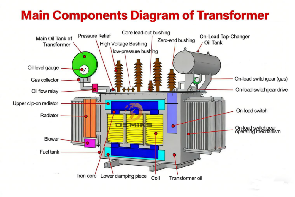
(2) Auxiliary components: Auxiliary components are important supports to ensure the normal operation of transformers. They mainly include bushings, tap changers, oil tanks, radiators, oil conservators, breathers, etc.
① Bushing: A bushing is a component that connects the transformer winding leads to the external circuit. Its main functions are to insulate and fix the leads, preventing short circuits between the leads and the tank. Medium and high voltage transformers typically use porcelain bushings or composite bushings, and their insulation performance and mechanical strength must meet the requirements of high voltage operation.
② Tap changer: The tap changer is a component that regulates the output voltage of the transformer. Its main function is to adjust the output voltage by changing the turns ratio of the windings, so that the output voltage is maintained within the rated range. Tap changers for medium and high voltage transformers are divided into off-load tap changers and on-load tap changers. Off-load tap changers need to be adjusted after the transformer is shut down, while on-load tap changers can be adjusted when the transformer is under load.
③ Oil Tank: The oil tank is the outer shell of the transformer. Its main function is to contain insulating oil and protect internal components from damage caused by the external environment. The oil tank of medium and high voltage transformers is usually welded from steel plates. The oil tank is equipped with components such as an oil drain valve, an oil drain hole, and a grounding terminal for easy maintenance and repair.
④ Radiator: The radiator is the cooling component of the transformer. Its main function is to dissipate the heat generated during transformer operation into the air, reduce the temperature of the insulating oil, and ensure the normal operation of the transformer. Radiators for medium and high voltage transformers mainly include plate radiators, tubular radiators, and corrugated radiators. Large-capacity high voltage transformers usually use forced oil circulation cooling systems (OFAF) or forced oil circulation guided cooling systems (ODAF).
⑤ Oil Conservator: The oil conservator is the oil replenishment component of the transformer. Its main function is to compensate for the volume expansion and contraction of the insulating oil due to temperature changes, maintain a stable oil level in the tank, and prevent the insulating oil from direct contact with air, thus reducing oil quality deterioration. The oil conservator is equipped with components such as an oil level gauge and a breather for easy observation of the oil level and protection of the insulating oil.
⑥ Breather: The breather is a protective component of the transformer. Its main function is to filter moisture and dust from the air, preventing moisture and dust from entering the oil conservator and oil tank, which could lead to deterioration of the insulating oil and corrosion of internal components. The breather contains a desiccant (such as silica gel). The desiccant will change color after absorbing moisture, making it easy to replace in a timely manner.
(3) Protection devices: Protection devices are an important guarantee to prevent major faults in transformers. They mainly include gas protection, longitudinal differential protection, instantaneous overcurrent protection, overload protection, temperature protection, etc.
① Gas protection: Gas protection is the core protection device of the transformer. Its main function is to detect internal faults in the transformer (such as winding short circuit, core overheating, insulation oil deterioration, etc.). When a fault occurs inside the transformer, gas will be generated at the fault point. The gas relay will activate, issue a warning signal or cut off the power supply to prevent the fault from spreading.
② Longitudinal differential protection: The main function of longitudinal differential protection is to detect short-circuit faults in transformer windings, bushings and other components. When a short-circuit fault occurs, the differential current exceeds the set value, the protection device operates, cuts off the power supply, and protects the transformer equipment.
③ Overload protection: The main function of overload protection is to detect the load current of the transformer. When the load current exceeds the rated value, the protection device issues an early warning signal to remind the operators to adjust the load in time to prevent the transformer from operating under overload for a long time, which would lead to winding aging and equipment damage.
④ Temperature protection: The main function of temperature protection is to detect the winding temperature and top oil temperature of the transformer. When the temperature exceeds the set limit, the protection device will issue a warning signal or cut off the power supply to prevent the transformer from aging of insulation and damage to equipment due to high temperature.
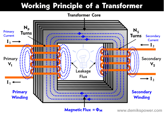
2.2 Working principle of medium and high voltage transformers
The working principle of medium and high voltage transformers is based on the law of electromagnetic induction, mainly realizing the conversion and transmission of electrical energy. Its core is to convert the electrical energy input from the primary side into electrical energy output at different voltage levels through the electromagnetic coupling between the primary and secondary windings. The specific working principle is as follows:
When the primary winding of a transformer is connected to an AC power source, the AC current flows through the primary winding, generating an alternating magnetic field. This alternating magnetic field forms a closed magnetic circuit through the iron core and passes through the secondary winding. According to the law of electromagnetic induction, an induced electromotive force (EMF) is generated in the secondary winding. The magnitude of this induced EMF is related to the turns ratio of the primary and secondary windings and the primary input voltage. The calculation formula is as follows:
Where, is the rated voltage of the primary winding, is the rated voltage of the secondary winding, is the number of turns in the primary winding, is the number of turns in the secondary winding, and is the transformer turns ratio.
When a transformer operates under load, an induced current is generated in the secondary winding. This induced current forms a loop through the load, and the magnetic field generated by the secondary current interacts with the magnetic field generated by the primary current. According to Lenz’s law, the secondary magnetic field opposes the change in the primary magnetic field, causing the primary current to increase, thus realizing the transfer of electrical energy. Ideally, the transformer’s input power equals its output power, i.e.:
Where is the primary side input power and is the secondary side output power.
However, in actual operation, transformers will generate certain losses, mainly including copper losses and iron losses:
(1) Copper loss: Copper loss is the loss generated by the resistance of the transformer winding. It is proportional to the square of the winding current and the winding resistance. It mainly occurs in the primary winding and secondary winding. Copper loss will only occur when the transformer is under load. The larger the load current, the greater the copper loss.
(2) Iron loss: Iron loss is the loss generated by the transformer core under the action of alternating magnetic field. It mainly includes hysteresis loss and eddy current loss. It is related to the material of the core, the magnetic field strength and the power supply frequency. Iron loss will also be generated when the transformer is running under no-load. The magnitude of iron loss is not related to the load current, but only to the power supply voltage and frequency.
During the operation of medium and high voltage transformers, the heat generated by copper and iron losses is dissipated through insulating oil and radiators, keeping the transformer temperature within the allowable range and ensuring normal operation. Simultaneously, the turns ratio of the primary and secondary windings is adjusted by tap changers to maintain the secondary output voltage within the rated range, meeting the user’s power needs.
2.3 Common Fault Types and Hazards of Medium and High Voltage Transformers
2.3.1 Common Fault Types
Medium and high voltage transformers have complex structures and operate under harsh conditions. Various components are prone to failure during long-term operation. Based on the component where the failure occurs, common faults can be categorized into six main types: winding faults, core faults, insulation faults, insulating oil faults, bushing faults, and tap changer faults. These are detailed below:
(1) Winding faults: Winding faults are one of the most common types of faults in medium and high voltage transformers, accounting for more than 30% of the total number of transformer faults. They mainly include winding short circuits, winding open circuits, winding deformation, and winding insulation aging.
① Winding short circuit: Winding short circuits are classified into inter-turn short circuits, inter-layer short circuits, and phase-to-phase short circuits. The main causes are aging or damage to the winding insulation, poor welding of the winding conductors, moisture in the winding, and foreign objects entering the winding. An inter-turn short circuit refers to a short circuit between adjacent turns of the same winding; an inter-layer short circuit refers to a short circuit between different layers of the same winding; and a phase-to-phase short circuit refers to a short circuit between different windings.
② Winding open circuit: The main causes of winding open circuit are broken winding wires, detached solder joints, mechanical damage to the winding, etc. Winding open circuit will cause the transformer to be unable to output electrical energy normally, and may even cause other faults.
③ Winding deformation: The main causes of winding deformation are mechanical impact during transformer transportation and installation, electrodynamic forces generated when the transformer experiences a short circuit fault, and overheating and deformation of the conductors due to long-term overload operation of the windings. Winding deformation can lead to damage to the winding insulation and cause short circuit faults.
④ Winding insulation aging: The main reason for winding insulation aging is that the transformer operates at high temperature for a long time. The insulation material is subjected to the combined effects of electric field, magnetic field and temperature. The insulation oil deteriorates, leading to a decrease in insulation performance. Winding insulation aging will reduce insulation strength and easily cause short circuit faults.
(2) Core faults: Core faults account for about 20% of all transformer faults, mainly including multiple grounding of the core, local overheating of the core, aging of the core insulation, and damage to the silicon steel sheets of the core.
① Multiple grounding of iron core: Multiple grounding of iron core is the most common iron core fault. The main reasons are damage to the iron core insulation layer, foreign objects entering the iron core, and moisture in the iron core. Multiple grounding of iron core will cause the iron core to form a closed loop, generate eddy currents, and cause local overheating of the iron core.
② Local overheating of the iron core: The main reasons for local overheating of the iron core are multiple grounding of the iron core, poor stacking of silicon steel sheets in the iron core, oil stains, dust and other contaminants on the surface of the iron core. Local overheating of the iron core can lead to aging of silicon steel sheets, damage to insulation materials, and even fire.
③ Core insulation aging: The main reason for core insulation aging is that the transformer operates at high temperature for a long time. The insulation material is affected by temperature and humidity, and the insulating oil deteriorates. Core insulation aging will lead to a decrease in the insulation performance of the core and easily cause multi-point grounding faults.
④ Damage to silicon steel sheets in the core: The main reasons for damage to silicon steel sheets in the core are mechanical impacts during the transportation and installation of the transformer, and long-term high-temperature operation of the core leading to aging and embrittlement of the silicon steel sheets. Damage to silicon steel sheets will increase the magnetic loss of the core, and increase the no-load current and no-load loss.
(3) Insulation faults: Insulation faults account for about 25% of the total number of transformer faults. They mainly include winding insulation breakdown, bushing insulation breakdown, lead wire insulation damage, insulation dampness, etc. Insulation faults are one of the main causes of transformer short circuits and shutdowns.
① Winding insulation breakdown: The main causes of winding insulation breakdown are aging of the winding insulation, moisture, overvoltage, and deterioration of the insulating oil. Winding insulation breakdown will lead to winding short circuit and cause transformer failure.
② Bushing insulation breakdown: The main causes of bushing insulation breakdown are aging and damage of bushing insulation, dampness of the bushing, dirt on the bushing surface, and overvoltage. Bushing insulation breakdown can lead to a short circuit between the lead wire and the oil tank, causing transformer failure.
③ Lead insulation damage: The main causes of lead insulation damage are mechanical damage to the lead, aging of insulation materials, and overvoltage. Lead insulation damage can lead to short circuits between leads and between leads and the iron core.
④ Insulation dampness: The main reasons for insulation dampness are poor transformer sealing, allowing moisture to enter the transformer, failure of the breather desiccant, and excessive moisture content in the insulating oil. Insulation dampness will lead to a decrease in insulation performance and easily cause insulation breakdown faults.
(4) Insulating oil failure: Insulating oil failure accounts for about 15% of the total number of transformer failures. It mainly includes insulating oil deterioration, insulating oil dampness, impurities mixed in the insulating oil, and reduced insulating oil breakdown voltage.
① Insulating oil deterioration: The main reason for the deterioration of insulating oil is that the transformer operates at high temperature for a long time. The insulating oil undergoes an oxidation reaction when it comes into contact with air. The insulating oil is also affected by electric and magnetic fields, and impurities are mixed into the insulating oil. The deterioration of insulating oil will lead to a decrease in its insulation and cooling performance, and it will be unable to play its role in insulation and cooling.
② Insulating oil gets damp: The main reasons for insulating oil getting damp are poor transformer sealing, moisture entering the oil tank, failure of the breather desiccant, and contact between insulating oil and humid air. Insulating oil getting damp will reduce its breakdown voltage, increase the dielectric loss factor, and easily cause insulation breakdown faults.
③ Impurities mixed in insulating oil: The main reasons for impurities mixed in insulating oil are improper operation during transformer manufacturing and maintenance, foreign objects entering the oil tank, and incomplete filtration of insulating oil. Impurities will reduce the insulating performance of insulating oil and accelerate oil deterioration.
④ Reduced breakdown voltage of insulating oil: The main reasons for the reduced breakdown voltage of insulating oil are moisture absorption, deterioration, and impurities. The reduced breakdown voltage will cause the insulating oil to be unable to withstand the rated voltage, which will easily lead to insulation breakdown faults.
(5) Bushing failures: Bushing failures account for about 5% of the total number of transformer failures. They mainly include bushing insulation aging, bushing damage, bushing surface dirt, bushing oil leakage, etc.
① Bushing insulation aging: The main reason for bushing insulation aging is that the bushing is exposed to the external environment for a long time, and is affected by sunlight, wind and rain, and temperature changes. The insulation material ages and becomes brittle, which leads to a decrease in the insulation performance of the bushing and makes it easy to cause insulation breakdown faults.
② Bushing damage: The main causes of bushing damage are mechanical impact, lightning strike, overvoltage, etc. Bushing damage will lead to leakage of insulating oil, decrease insulation performance, and cause short circuit faults.
③ Bushing surface contamination: The main reason for bushing surface contamination is dust, oil, etc. from the external environment adhering to the bushing surface. Especially in humid environments, contamination will lead to a decrease in the insulation performance of the bushing surface and make it prone to flashover faults.
④ Bushing oil leakage: The main cause of bushing oil leakage is poor bushing sealing, aging or damage of the sealing ring, etc. Oil leakage will lead to a drop in insulating oil level, a decrease in the insulation and cooling performance of the transformer, and may also cause a fire.
(6) Tap changer failure: Tap changer failure accounts for about 5% of the total number of transformer failures. It mainly includes poor contact of tap changer, tap changer jamming, tap changer insulation aging, tap changer oil leakage, etc.
① Poor contact of tap changer: The main reason for poor contact of tap changer is wear and oxidation of tap changer contacts, oil stains, dust, etc. on the contact surface. Poor contact of tap changer will cause the contacts to heat up, or even generate electric arc, damage the contacts and insulation, and cause short circuit fault.
② Tap switch jamming: The main reasons for tap switch jamming are wear and corrosion of mechanical parts of the tap switch, dry lubricating oil, etc. Tap switch jamming will prevent the tap position from being adjusted normally, affecting the stability of transformer output voltage.
③ Tap changer insulation aging: The main reason for tap changer insulation aging is long-term high-temperature operation, the insulation material is affected by electric and magnetic fields, and the insulating oil deteriorates. Insulation aging will lead to a decrease in the insulation performance of the tap changer, which can easily cause short circuit faults.
④ Tap changer oil leakage: The main cause of tap changer oil leakage is poor sealing, aging or damage of the sealing ring, etc. Oil leakage will lead to leakage of insulating oil, affecting the insulation and cooling performance of the transformer.
2.3.2 Hazards of the Fault
As core equipment in the power system, medium and high voltage transformers are susceptible to damage. Their failures not only damage the equipment itself but also affect the safe and stable operation of the power system, causing significant economic losses and social impacts. Specific hazards include:
(1) Harm to the transformer itself: When a transformer fails, it will cause damage to internal components, such as burnt windings, overheated core damage, and insulation breakdown. In severe cases, it will lead to the scrapping of the transformer, requiring a large amount of money to repair or replace it, increasing the operating costs of power companies. At the same time, the failure will shorten the service life of the transformer. The original design service life of a transformer is 20 to 30 years. If the failure occurs frequently, the service life may be shortened to 10 to 15 years.
(2) Harm to the power system: Faults in medium and high voltage transformers can lead to power outages or a decline in power quality. For example, a fault in the main transformer of a substation can cause a power outage at the entire station, affecting the normal power supply of surrounding transmission lines and users; a fault in a transformer in a long-distance transmission line can cause a power outage, resulting in a power supply gap; a short circuit fault caused by a transformer fault can generate a huge short circuit current, damaging other equipment in the power system (such as circuit breakers, disconnect switches, etc.), expanding the scope of the fault, and even causing the collapse of the power system.
(3) Harm to the economy and society: Power outages caused by transformer failures can have a serious impact on industrial production, residents’ lives, and various social undertakings. Power outages in industrial enterprises can lead to production interruptions and cause substantial economic losses, especially for enterprises with continuous production, where a one-hour power outage can result in losses of millions or even tens of millions of yuan; power outages in residential areas can disrupt normal life, affecting services such as lighting, water supply, and heating; power outages in important locations such as hospitals, schools, and transportation hubs can affect normal operations and even cause safety accidents, resulting in serious social impacts.
(4) Safety hazards: Transformer malfunctions may cause safety accidents such as fires and explosions, threatening the lives and property of personnel. For example, short circuits in the windings and overheating of the core can cause the insulating oil to burn and cause a fire; if the insulating oil leaks and comes into contact with an open flame, it can cause an explosion; the electric arc generated by the malfunction can burn personnel and damage surrounding equipment.
In conclusion, faults in medium and high voltage transformers pose a significant threat. Therefore, it is essential to strengthen transformer inspection, promptly identify potential faults, and implement targeted maintenance and repair measures to prevent faults and ensure the safe and stable operation of transformers and the power system.
2.4 Chapter Summary
This chapter primarily introduces the fundamental theories of medium- and high-voltage transformers, defines their voltage level ranges, analyzes their structural components (core components, auxiliary components, and protection devices) and working principles, and outlines common fault types (winding faults, core faults, insulation faults, insulating oil faults, bushing faults, and tap changer faults) and their mechanisms. It also elucidates the harm these faults cause to the transformer itself, the power system, and the economy and society. Through this chapter, the core characteristics and fault risks of medium- and high-voltage transformers are clarified, laying a theoretical foundation for subsequent research on testing systems, testing items, testing equipment, and the significance of testing. Medium- and high-voltage transformers have complex structures, operate under harsh conditions, have a high fault rate, and their faults cause significant damage. Therefore, establishing a scientific and comprehensive testing system, employing precise and efficient testing technologies and equipment, and conducting all-round testing is of great necessity and urgency.
Chapter 3 Overview of the Testing System for Medium and High Voltage Transformers
3.1 Classification and Applicable Scenarios of Medium and High Voltage Transformer Testing
The testing of medium and high voltage transformers is a systematic process that spans the entire lifecycle of the transformer (manufacturing, transportation, installation, operation, maintenance, and scrapping). Based on the different stages, purposes, and requirements of the testing, it can be divided into five main categories: factory testing, acceptance testing, routine testing, type testing, and special testing. The applicable scenarios, testing objectives, and core requirements of each type of testing differ significantly, as detailed below:
3.1.1 Factory test
Factory testing is a mandatory test conducted after the transformer is manufactured and before it leaves the factory. It is the first line of defense to ensure the quality of transformer products. Every medium and high voltage transformer must undergo factory testing and can only leave the factory after passing the test.
(1) Applicable scenarios: After the transformer is manufactured, this process is carried out in the manufacturing plant, mainly for each transformer leaving the factory, to ensure that the quality of the transformer meets the design requirements and national standards.
(2) Purpose of testing: To verify the manufacturing quality of the transformer, check whether the structure and performance of the transformer meet the design requirements and national standards, and promptly detect defects in the manufacturing process (such as poor winding welding, loose core stacking, damaged insulation layer, and damp insulating oil), so as to ensure that each transformer leaving the factory can meet the basic conditions for safe and stable operation and prevent unqualified products from entering the market and power system.
(3) Core requirements: Factory tests must be strictly carried out in accordance with the GB/T 1094 series of national standards and transformer design documents. Each medium and high voltage transformer must be issued a complete factory test report, which must include the test items, test data, pass/fail results, signature of the test personnel and test date, etc. If any non-conformities are found during the test, they must be repaired and reworked in time, and can only be released from the factory after passing the retest. For high voltage and ultra-high voltage transformers, some key test items (such as partial discharge test and withstand voltage test) must be carried out in the manufacturing plant to simulate the actual operating conditions to ensure the accuracy and reliability of the test results.
(4) Specific testing items: Factory testing is divided into two parts: routine testing and type testing. Routine testing is mandatory for every unit, while type testing is conducted when sampling or finalizing products of the same model (to be described separately later). The core testing items for routine factory testing are as follows, all of which require corresponding dedicated testing equipment:
① Winding DC resistance measurement: Check the winding welding quality, conductor cross-section consistency and tap changer contact status. Use a transformer DC resistance tester. For medium voltage transformers, select a range of 10A~50A. For high voltage transformers, select a range of 100A~200A with magnetizing function. The measurement data must meet the design requirements. The three-phase winding resistance imbalance rate must meet the requirements of ≤4% for medium voltage and ≤2% for high voltage.
② Transformer ratio and winding group measurement: Verify whether the winding ratio is consistent with the nameplate marking and whether the winding group connection is correct. Use a transformer ratio and group tester to automatically calculate the ratio error and determine the group. The ratio error must be controlled within ±0.5%, and the group must be completely consistent with the nameplate to avoid the transformer from failing to operate normally due to ratio deviation or incorrect group.
③ Winding insulation resistance, absorption ratio/polarization index measurement: Assess the degree of moisture and contamination of winding insulation using an insulation resistance tester (megohmmeter) with a range of 2500V~10000V. For medium-voltage transformers, use a 2500V range; for high-voltage transformers, use a 5000V~10000V range. High-voltage transformers require a polarization index ≥1.3 and an absorption ratio ≥1.2. The insulation resistance value must meet the national standard limits.
④ Dielectric loss factor (tanδ) and capacitance measurement: Inspect the overall aging and moisture defects of the winding and bushing insulation. Use an anti-interference frequency dielectric loss tester. For medium-voltage transformers, use a conventional frequency type, and for high-voltage transformers, use a strong anti-interference type (frequency range 40Hz~60Hz). The measurement accuracy should be ≤0.0001. The dielectric loss factor measurement value should meet the design requirements and the deviation from the factory standard value should not exceed 30%.
⑤ Insulating oil performance test: Test the electrical strength, moisture content, dielectric loss characteristics, etc. of the insulating oil using an insulating oil dielectric strength tester (such as DJC-202), an insulating oil moisture tester (such as DJC-203), and an insulating oil dielectric loss tester. The DJC-202 has a step-up range of 0~80kV, and the DJC-203 has a measurement accuracy of ≤1ppm. The insulating oil breakdown voltage is ≥30kV for medium voltage and ≥40kV for high voltage, and the moisture content is ≤10ppm (≤5ppm for high voltage transformers).
⑥ No-load loss and no-load current measurement: Verify the magnetic properties and assembly quality of the iron core, judge the defects in the stacking of silicon steel sheets in the iron core, and use a transformer comprehensive testing system. For medium-voltage transformers, select an integrated system with a range of ≤100kVA, and for high-voltage transformers, select a system with a range of ≥500kVA that supports accurate measurement of low power factor. The no-load loss and no-load current must meet the design requirements, and the deviation shall not exceed ±10% of the design value.
⑦ Short-circuit impedance and load loss measurement: Verify whether the winding impedance characteristics and load loss meet the design values. Use a transformer comprehensive test system. For high-voltage and large-capacity transformers, a system with temperature rise compensation function should be selected to eliminate the influence of winding temperature changes on the measurement results during the test. The measured values of short-circuit impedance and load loss must meet the design requirements, and the deviation should not exceed ±5% of the design value.
⑧ Core grounding current measurement: Check whether the single-point grounding of the core is reliable and avoid local overheating caused by multiple grounding. Use a transformer core grounding current tester, which supports non-contact clamp measurement. The current measurement range is 0~10A, and the accuracy is ≤0.1mA. The core grounding current must be ≤100mA to ensure that the core grounding is reliable and there is no abnormal circulating current.
⑨ Power frequency withstand voltage test (short time): Verify the short-time power frequency insulation withstand capability of windings and bushings. Use a power frequency withstand voltage test device. For medium-voltage transformers, use a 50kV~100kV device, and for high-voltage transformers, use a 200kV~1000kV device. The test voltage is 2~3 times the rated voltage, and the duration is 1 minute. It is considered qualified if there is no insulation breakdown or flashover during the test.
3.1.2 Routine Tests
Routine testing is a regular, routine inspection conducted periodically after a transformer is put into operation. It falls under the category of preventative testing. Its core purpose is to monitor the transformer’s operating status in real time, promptly identify potential faults caused by factors such as aging, wear, and moisture during operation, provide a scientific basis for maintenance and repair work, and extend the transformer’s service life.
(1) Applicable scenarios: After the transformer is put into operation, it is carried out at the actual operation site such as substation and power plant. The testing cycle is determined according to the voltage level, capacity and operating conditions of the transformer. It is applicable to all high voltage transformers in operation and is an indispensable link in the whole life cycle management of transformers.
(2) Purpose of inspection: To monitor the changing trend of transformer operating status, and to promptly detect potential fault hazards such as winding aging, multi-point grounding of iron core, deterioration of insulating oil, and dirty bushings during operation; to verify whether the operating performance of the transformer still meets national standards and design requirements, and to determine whether the transformer can continue to operate safely and stably; to provide accurate basis for maintenance and repair work, to avoid the waste of manpower, material resources and financial resources caused by blind repair, and to achieve the goal of “condition-based maintenance”.
(3) Core requirements: Routine tests must be carried out in strict accordance with national standards such as GB/T 1094.1-2013 and GB 50150-2016 and the operation and maintenance procedures of power companies. Based on the specific specifications and years of operation of the transformer, a personalized testing cycle should be formulated (such as once a year or once every two years; the testing cycle for high-voltage and ultra-high-voltage transformers can be appropriately shortened). Safety protection measures should be taken during the testing process to avoid affecting the normal operation of the transformer. If abnormal data is detected, it is necessary to compare it with historical data in a timely manner, analyze the cause of the abnormality, and take targeted maintenance measures. After the test is completed, the test data should be organized in a timely manner, and a transformer operation and maintenance file should be established to achieve full traceability of the test data.
(4) Specific testing items and equipment requirements: The testing items for routine tests overlap with those for factory tests, but the focus of testing is more on “condition monitoring”. The core testing items are as follows. The compatible equipment is basically the same as that for factory tests, but the special characteristics of the on-site operating environment (such as anti-interference and portability) need to be considered:
① Winding DC resistance measurement: Regularly check the winding resistance value and three-phase imbalance rate, compare the factory data with historical test data, and determine whether there are problems such as poor contact, wire aging, tap changer wear. Use a portable transformer DC resistance tester. For high-voltage transformers, a model with magnetizing function should be selected for easy on-site operation. The deviation of the measurement data should be controlled within ±5% of the historical data.
② Retesting of turns ratio and winding group: Retesting should be conducted every 3 to 5 years to verify whether the winding turns ratio has deviated due to vibration and wear during operation, and whether the group connection is reliable. A portable transformer turns ratio and group tester should be used to ensure that the turns ratio error is still controlled within ±0.5% and the group has not changed, so as to avoid the power supply quality being affected by turns ratio deviation.
③ Winding insulation resistance, absorption ratio/polarization index measurement: Test every 1 to 2 years, especially after the rainy season or humid environment, the testing frequency needs to be increased to assess the degree of moisture and aging of the winding insulation. Use a portable 2500V/5000V megohmmeter. For high-voltage transformers, the trend of polarization index and absorption ratio changes needs to be monitored. If the values drop significantly (e.g., polarization index < 1.3), the potential for moisture or aging of the insulation needs to be investigated in time.
④ Dielectric loss factor (tanδ) and capacitance measurement: Test every 2-3 years, and high voltage and ultra-high voltage transformers should be tested annually. Use a portable anti-interference frequency dielectric loss tester. On-site, use the frequency method to eliminate power grid interference and measure the dielectric loss factor of windings and bushings. Compare with historical data. If the dielectric loss factor increases by more than 30%, it is necessary to determine whether the insulation is aging, damp, or has local defects, and take insulation treatment measures in a timely manner.
⑤ Periodic testing of insulating oil performance: This is a key item in routine testing. The testing cycle is determined based on the number of years of operation. Newly commissioned transformers should be tested every 6 months, and transformers that have been in operation for more than 1 year should be tested annually. Core testing items include breakdown voltage, moisture content, dielectric loss factor, acid value, and closed-cup flash point. Portable insulating oil testing equipment (such as portable DJC-202 insulating oil dielectric strength tester, DJC-203 insulating oil micro-moisture tester, fully automatic water-soluble acid value tester, and closed-cup flash point tester) should be used. Specific requirements are as follows:
– Breakdown voltage: Medium voltage transformer ≥30kV, high voltage transformer ≥40kV. If the value drops by more than 10kV, the insulating oil needs to be filtered and dried.
– Moisture content: Medium voltage transformer ≤15ppm, high voltage transformer ≤10ppm, ultra-high voltage transformer ≤5ppm. If the moisture content exceeds the standard, the desiccant in the breather must be replaced in time and the insulating oil must be dehydrated.
– Dielectric loss factor (90℃): ≤0.005, if it exceeds the standard, the insulating oil needs to be replaced;
– Acid value: ≤0.03mgKOH/g. An acid value exceeding the standard indicates that the insulating oil has undergone oxidation and deterioration and needs to be replaced in time.
– Closed-cup flash point: ≥140℃. A decrease in flash point indicates that flammable impurities have been mixed into the insulating oil, and leaks and potential pollution hazards need to be investigated.
⑥ Core grounding current measurement: Monitor once a month using a portable transformer core grounding current tester. Use a clamp probe for non-contact measurement. The core grounding current should be ≤100mA. If the current increases significantly (e.g., exceeds 200mA), it indicates that there is a multi-point grounding fault in the core. The cause of the grounding should be investigated and eliminated in time to avoid local overheating of the core.
⑦ Partial discharge detection: High-voltage transformers (66kV and above) should be inspected once a year, and ultra-high-voltage transformers should be inspected every 6 months. A portable partial discharge detection system should be used, employing a combined ultrasonic and electrical testing method. The detection accuracy should be ≤1pC, and the partial discharge should be controlled within ≤10pC (high voltage) and ≤5pC (ultra-high voltage). If the partial discharge increases significantly, the location of the partial discharge should be identified, and insulation defects should be investigated.
⑧ Winding and top oil layer temperature monitoring: Real-time monitoring during daily operation, using temperature sensors and online monitoring systems, and regular verification of temperature measurement data to ensure that the winding temperature is ≤105℃ and the top oil layer temperature is ≤95℃. If the temperature rises abnormally, it is necessary to check for overload, cooling system failure or internal heating defects (such as winding short circuit or local overheating of the iron core).
3.1.3 Handover Test
The handover test is a one-time inspection conducted after the transformer is transported and installed, but before it is put into operation. Its core purpose is to verify whether the transformer has been damaged during transportation and installation, whether the installation quality meets the requirements, and to ensure that the transformer can be put into safe operation. It is a key inspection link connecting “factory delivery” and “operation”.
(1) Applicable scenarios: The handover test is conducted at the installation site of the transformer after it has been delivered to the site, installed and commissioned, and before it is put into operation. It is applicable to all newly installed, overhauled or modified medium and high voltage transformers. Regardless of whether they have undergone factory testing, they must undergo handover testing and can only be put into operation after passing the test.
(2) Purpose of testing: To verify whether the transformer has been damaged during transportation (such as vibration and impact), such as winding deformation, core loosening, insulation damage, and insulating oil leakage; to verify whether the installation process (such as winding lead connection, bushing installation, core grounding, and cooling system installation) meets the design requirements and installation procedures; to compare the factory test data to determine whether the transformer performance has changed, to promptly identify new defects generated during transportation and installation, and to avoid failures caused by transportation and installation damage after the transformer is put into operation.
(3) Core requirements: The handover test must be carried out in strict accordance with GB 50150-2016 “Standard for Handover Test of Electrical Equipment in Electrical Installation Engineering”. The test items must cover the core items of the factory test, and the test standards for some items are more stringent than those of the factory test. During the test, close cooperation with the installation unit, supervision unit and manufacturing unit is required to record and verify the test data. If any unqualified items are found during the test, the installation unit or manufacturing unit must repair and handle them, and the transformer can only be put into operation after passing the retest. After the handover test is completed, a complete handover test report must be issued as an important basis for the operation of the transformer and included in the transformer operation and maintenance file.
(4) Specific testing items and equipment requirements: The testing items for the handover test are basically the same as those for the routine factory test, but the focus of the test is on “transportation and installation damage investigation”. The testing standards for some items are more stringent. The core testing items and equipment requirements are as follows:
① Winding DC resistance measurement: Use a transformer DC resistance tester to test the winding resistance value, three-phase unbalance rate, and resistance value of each tap position. Compare with the factory test data. The deviation should be controlled within ±2%. The three-phase resistance unbalance rate should be ≤4% for medium-voltage transformers and ≤2% for high-voltage transformers. The resistance value of each tap position should be uniform without significant fluctuations to avoid poor contact of the tap position or loosening of the winding leads due to transportation vibration.
② Measurement of turns ratio and winding group: Use a transformer turns ratio and group tester to fully retest the winding turns ratio and group. The turns ratio error must be ≤ ±0.5%, and the group must be consistent with the nameplate and factory test report to ensure that no winding connection error or turns ratio deviation occurs during transportation and installation.
③ Winding insulation resistance, absorption ratio/polarization index measurement: Use a 2500V/5000V megohmmeter to test the winding insulation resistance, absorption ratio (for 10kV and above transformers), and polarization index (for 220kV and above transformers). For high-voltage transformers, the polarization index should be ≥1.3, the absorption ratio should be ≥1.2, and the insulation resistance value should not be less than 70% of the factory test value. If the value drops significantly, it is necessary to check whether the winding insulation has been damp or damaged during transportation or installation.
④ Dielectric loss factor (tanδ) and capacitance measurement: Use an anti-interference heterodyne dielectric loss tester. On-site, use heterodyne method to eliminate power grid interference and test the dielectric loss factor and capacitance value of windings and bushings. Compare with the factory test data. The change in dielectric loss factor should be ≤30% and the change in capacitance value should be ≤5%. If the change exceeds the standard, it is necessary to check whether the insulation is damaged, damp or contaminated.
⑤ Insulating oil performance testing: After the transformer is installed, the breakdown voltage, moisture content, dielectric loss factor, and other items of the insulating oil need to be retested. The DJC-202 insulating oil dielectric strength tester, DJC-203 insulating oil moisture tester, and insulating oil dielectric loss tester should be used. The testing standards are as follows:
– Breakdown voltage: Medium voltage transformer ≥30kV, high voltage transformer ≥40kV, ultra-high voltage transformer ≥60kV;
– Moisture content: Medium voltage transformer ≤10ppm, high voltage transformer ≤5ppm, ultra-high voltage transformer ≤3ppm;
– Dielectric loss factor (90℃): ≤0.004, which must be better than the factory test standard;
If the performance of the insulating oil is substandard, it needs to be filtered, dried, or replaced to ensure that the insulating oil meets the operating requirements.
⑥ Core grounding current measurement: Use a transformer core grounding current tester to test the core grounding current. It must be ≤100mA and the grounding must be reliable to avoid multiple grounding points of the core due to foreign objects entering the core or damage to the insulation layer during installation.
⑦ Partial Discharge Detection: Partial discharge detection must be performed on high-voltage transformers (66kV and above) and ultra-high-voltage transformers. A partial discharge detection system should be used, employing a combined ultrasonic and electrical testing method. The detection accuracy should be ≤1pC. The partial discharge requirements are: ≤10pC for 66kV~220kV transformers and ≤5pC for 330kV and above transformers. If a partial discharge signal is detected, the discharge location must be identified, and insulation defects (such as winding insulation damage or bushing insulation damage) must be investigated.
⑧ Power Frequency Withstand Voltage Test: The power frequency withstand voltage test is a key item in the acceptance test. Its purpose is to verify whether the transformer insulation can still withstand the impact of the rated voltage after transportation and installation. A power frequency withstand voltage test device is used, and the test voltage is 80% of the factory test voltage (2 times × 80% of the rated voltage for medium voltage transformers and 1.5 times × 80% of the rated voltage for high voltage transformers). The test lasts for 1 minute. If there is no insulation breakdown or flashover during the test, it is considered qualified. Avoid damaging the transformer insulation due to excessive test voltage.
⑨ Cooling system test: Detect the operating status of the cooling system (radiator, forced oil circulation system), verify whether the cooling effect meets the design requirements, use a thermometer and flow meter to test the heat dissipation efficiency and oil circulation speed of the cooling system, and ensure that the transformer can effectively dissipate heat during operation.
⑩ Protection device verification: Verify the transformer’s protection devices (gas protection, longitudinal differential protection, overload protection, temperature protection, etc.) using a protection device verification instrument to ensure that the protection devices operate accurately and reliably, and that the operating values meet the design requirements, so as to avoid protection failure due to incorrect wiring or improper debugging during installation.
It is important to note that after the handover test is completed, the test data must be fully compared with the factory test data. If there is a significant deviation, the cause of the deviation must be analyzed and the manufacturing and installation units must work together to investigate and handle the issue, ensuring that the transformer is free from any transportation or installation damage before it can be put into operation. For transformers that have undergone major repairs or modifications, the handover test items can be appropriately adjusted according to the content of the repair or modification, but the core items (such as insulation resistance, withstand voltage test, partial discharge detection, etc.) must be fully covered.
3.2 Basic Principles of Medium and High Voltage Transformer Testing
The testing of medium and high voltage transformers (whether it is factory testing, routine testing, or acceptance testing) must follow the following core principles to ensure the scientific, standardized, accurate, and reliable nature of the testing work, thereby providing a guarantee for the safe and stable operation of the transformers.
(1) Standardization Principle: All testing work must be carried out in strict accordance with national standards (GB/T 1094 series, GB 50150-2016, etc.), industry standards, transformer design documents, and operation and maintenance procedures. Testing items, testing methods, technical requirements, and qualification standards must be unified to avoid data distortion and incorrect qualification judgments due to non-standard testing. Testing personnel must strictly follow the operating procedures to operate the testing equipment to ensure that the testing process is standardized and orderly.
(2) Accuracy principle: The accuracy of the test data is the core of the test work. Test equipment that meets the accuracy requirements and has been calibrated must be selected. Before the test, the equipment must be debugged and calibrated to ensure that the equipment is operating normally. During the test, the test environment (such as temperature, humidity and electromagnetic interference) must be strictly controlled to avoid environmental factors from affecting the test data. After the test is completed, the test data must be reviewed and analyzed to ensure that the data is true, accurate and without omissions or errors.
(3) Preventive principle: The core purpose of testing is to “prevent faults”. In particular, routine testing should adhere to the principle of “regular testing, early investigation and timely handling”. Through routine testing, we can grasp the changing trend of transformer operating status, discover potential fault hazards in time, take targeted maintenance and repair measures, prevent the fault from expanding, avoid power outage accidents caused by faults, realize the “condition maintenance” of transformers, and extend service life.
(4) Full life cycle principle: Testing work should be carried out throughout the entire life cycle of the transformer (manufacturing, transportation, installation, operation, maintenance, and scrapping). Factory testing ensures product quality, handover testing ensures installation quality, and routine testing ensures operational status. Testing work at different stages is interconnected and complementary to form a complete testing system to ensure that the entire process of the transformer from leaving the factory to scrapping can be effectively monitored and guaranteed.
(5) Safety principle: The testing work must adhere to the principle of “safety first”. In particular, routine tests and handover tests conducted on site must be carried out with safety protection measures and strictly abide by the power safety operation procedures to avoid safety accidents such as high voltage electric shock, equipment damage, and personnel injury. During the testing process, it is necessary to avoid affecting the normal operation of the transformer. If it is necessary to shut down the transformer for testing, a shutdown plan must be prepared in advance and safety measures such as power outage, voltage testing, and grounding must be taken to ensure that the testing work is carried out safely and orderly.
(6) Traceability principle: All testing work must be recorded and a complete testing file must be established, including testing reports, testing data, equipment calibration records, signatures of testing personnel, testing dates and other information. The testing file must be properly kept to ensure that the testing data is traceable and verifiable. For abnormal data and non-conforming items found during the testing process, the handling process and handling results must be recorded to form a closed-loop management and provide a reference for subsequent testing, maintenance and repair work.
More information for the transformer testing methods and HV transformer hipot withstand testing solutions please consult with our sales team from DEMIKS power.