


Transformer FAQs | Technical Questions & Answers
FAQ: Why must the transformer core be grounded?
The transformer core and its metal components have different potentials due to their different electric field positions.
When the potential difference between two points reaches a level sufficient to break down the insulation between them, a spark discharge occurs.
This discharge is intermittent; after each discharge, the potentials at both points are equal, and the discharge stops; then a potential difference is generated again, and the discharge resumes. This intermittent discharge causes the transformer oil to decompose and easily damages the solid insulation, leading to accidents.
To avoid this, the transformer core and other metal components must be connected to the tank and then grounded, ensuring they are at the same potential (zero potential).
If the transformer core is grounded at two points, it is equivalent to a short circuit on both sides of the core, generating a certain current.
This current leads to localized overheating, increased losses, and even the melting of the grounding plate, causing the core to have a floating potential, which is unacceptable.
FAQ: What are main magnetic flux and leakage flux?
When a winding in a transformer is connected to the power supply, magnetic flux is generated in the core. The magnetic flux generated in the core due to the excitation voltage is called the main magnetic flux.
When a load current flows through a transformer, a magnetic flux is generated around the windings. This magnetic flux generated by the load current within the windings is called leakage flux.
FAQ: How is the leakage flux distributed in the windings? What kind of mechanical force does it generate?
In a dual-winding transformer, the current directions are opposite. The current direction in the low-voltage winding is outward, represented by ⊙; the current direction in the high-voltage winding is inward, represented by ⊕. Determine the direction of the leakage flux using the right-hand rule (the thumb points in the direction of the current, and the four fingers point in the direction of the leakage flux). See the attached diagram.
Let’s see how the mechanical force is generated.
First, decompose the leakage flux into axial and radial directions. According to the left-hand rule: “Leakage flux passes through the palm, the four fingers point in the direction of the current, and the thumb points in the direction of the force.”
In the radial direction, due to the axial leakage flux: the low-voltage winding experiences an inward mechanical force; the high-voltage winding experiences an outward mechanical force.
In the axial direction, due to the radial leakage flux: both the high-voltage and low-voltage windings experience axial pressure. See the diagram. This shows why we need to place support bars and pads during winding: to reduce the mechanical force acting on the winding.
FAQ: What are the hazards of short-circuit current when a transformer is short-circuited?
If a short circuit occurs on the secondary side of a transformer during operation, the short-circuit current is very large, generally ten to twenty times the rated current. The electromagnetic force can increase hundreds or even thousands of times (F=B*I*L). Such a large electromagnetic force can cause the winding turns to deform at best, and break at worst. Simultaneously, the transformer oil temperature in the tank rises rapidly, the circuit breaker may not trip, and the transformer may burn out.
FAQ: What is the insulation level of a transformer? What is full insulation? Graded insulation?
Insulation level is the level at which a transformer can withstand various overvoltages and the highest long-term operating voltage during operation.
Full insulation: When all the leads of the winding have the same withstand voltage to ground, this insulation structure is called full insulation.
Graded insulation: When the insulation level of the neutral point of the winding is lower than the insulation level of the leads, the winding insulation structure is called graded insulation.
Insulation levels are shown in the table.
FAQ: What is the Insulation level to ground at the winding output terminals of transformers with voltage ratings of 3~500kV?
Insulation levels for transformer output terminals from 3kV to 500kV progressively increase, determined by voltage class, with requirements set by standards like IEC/IEEE, specifying Basic Impulse Levels (BIL) that rise from around 45kV (3.3kV) to 1800kV or more (500kV), ensuring withstand capability against switching/lightning surges, with specifics varying by winding, system grounding, and design, often using oil/paper or polymer insulation for reliability.
Here’s a breakdown by voltage range:
Medium Voltage (MV) (3.3kV – 33kV)
BIL: Typically 45kV to 170kV.
Purpose: Withstand standard switching surges and some lightning.
High Voltage (HV) (66kV – 230kV)
BIL: Ranges from 250kV to 750kV.
Details: Higher BILs required for higher system voltages
Extra-High Voltage (EHV) (275kV – 400kV)
BIL: From 900kV to 1550kV.
Example: A 500kV transformer might have a 1550kV line-side winding BIL, according to this Atlantis Press article.
Ultra-High Voltage (UHV) (500kV – 765kV)
BIL: Generally 1800kV to 2450kV.
Complexity: Insulation design becomes critical, handling large voltage changes, especially during faults, using specialized materials like modified silicone rubber.
Key Factors & Standards
Standards: Governed by IEEE C57.12.00/C57.12.90 and IEC 60076.
BIL (Basic Impulse Level): The peak voltage of a standard lightning impulse the insulation must withstand.
Terminal Insulation: Porcelain or resin bushings provide external insulation, preventing flashover.
In essence, as the transformer’s rated voltage climbs, so does the required insulation strength (BIL) to protect against system transients.
FAQ: How is transformer insulation classified? What are the different parts of the insulation?
The insulation of oil-immersed transformers is mainly divided into two categories: internal insulation and external insulation.
Internal insulation: Consists of main insulation and longitudinal insulation.
Main insulation: This is the insulation between the winding and the core, to ground, and to other windings; that is, the insulation between various components within the transformer. (Low-voltage winding insulation to the core uses bakelite tubes; high-voltage winding insulation uses cardboard tubes; dry-type transformers use epoxy glass cloth tubes.)
Longitudinal insulation: This includes the outer insulation of the conductors, the layer insulation of cylindrical windings, the insulation between the electrostatic ring and the wire segments, and the insulation between wire segments (layers).
Common transformer main insulation components (see diagram below)
External insulation: This includes the external insulation of the bushing itself, and the insulation between bushings and between bushings and ground.
FAQ: What are insulating materials? How many levels are there?
Materials with a very high resistivity, reaching 10²Ω·cm²/cm, but with negligible current flowing through them, are called insulating materials.
| INSULATION LAYER | Y | A | E | B | F | H | C |
| Heat resistance temperature/℃: | 90 | 105 | 120 | 130 | 155 | 180 | 180 Above |
Insulating materials are classified into seven grades according to their heat resistance, namely…
Oil-immersed transformers use Class A insulation.
Dry-type transformers come in two types: cast iron type (Class F insulation) and open type (Class H insulation).
FAQ: Why shouldn’t the transformer upper oil temperature be too high (not exceeding 85℃)?
Upper oil temperature: The oil temperature gauge measures the upper oil temperature or temperature rise of the transformer.
Oil-immersed transformers use Class A insulation. 105℃ is the maximum allowable average operating temperature. The winding average temperature rise limit is 65℃, and the upper oil temperature rise limit is 55℃. To ensure the transformer oil doesn’t age rapidly over long-term operation, the upper oil temperature should not frequently exceed 85℃.
There’s a 6-degree rule for insulation materials: The maximum allowable temperature for Class A insulation materials is 105℃. For every 6℃ increase in temperature, the insulation life is halved.
FAQ: Why is the transformer winding temperature generally set at 65°C?
Transformer winding temperature is typically set at 65℃ (this is actually the winding temperature rise limit, not an absolute temperature). The core reason for this is to balance the lifespan of insulation materials with operational reliability:
Insulation Material Heat Resistance :The maximum allowable operating temperature of commonly used Class A insulation materials in transformers (such as oil-paper insulation) is 105℃, while the winding temperature rise is calculated as “winding temperature – ambient temperature.”
If the ambient temperature is calculated at 40℃ (the standard reference ambient temperature for power equipment), 105℃ – 40℃ = 65℃, which is the rated temperature rise limit for Class A insulation windings.
Exceeding this temperature rise will drastically accelerate the aging rate of the insulation material (for every 8~10℃ increase in temperature, the insulation life is halved, i.e., the “thermal aging law”).
Balance between Operational Safety and Economy:: Setting the temperature rise to 65℃ ensures stable operation of the insulation material within its design life (typically 20~30 years) while avoiding excessively restricting the temperature rise, which would lead to excessively large equipment size and high costs.
Simply put: 65℃ is the winding temperature rise limit for a Class A insulated transformer at 40℃, after balancing insulation life and operating costs.
FAQ: Why do oil-immersed transformers use an oil-paper insulation structure?
We know that one of the functions of transformer oil is insulation. Treated transformer oil can achieve an electrical strength of over 40kV/mm;
(for products above 35kV)
For 6-35kV transformers, the electrical strength of the oil is above 35kV/mm;
However, as the gaps in the transformer oil gradually increase, its insulation strength per millimeter decreases. When the oil gap spacing is 3mm, the insulation strength of the oil gap is 141kV/mm; when the oil gap spacing is 6mm, the insulation strength of the oil gap is 101kV/mm. Therefore, adding a piece of paper in the oil gap can improve the insulation strength of the oil; the smaller the gap, the higher the insulation strength.
This is the reason for using an oil-paper insulation structure.
Furthermore, the material is readily available and the manufacturing process is simple.
Transformer oils are available in DB-10, DB-25, and DB-45.
DB-10: Indicates a pour point of -10℃.
DB-25: Indicates a pour point of -25℃; also known as No. 25 transformer oil.
DB-45: Indicates a pour point of -45℃; also known as No. 45 transformer oil, used in cold regions.
Transformer oil is refined from petroleum. Transformer oils from different origins cannot be mixed due to their different oil bases.
(Oil bases include paraffinic, aromatic, naphthenic, and mixed bases, etc. Different oil bases have different aging rates and therefore cannot be mixed.)
FAQ: Why is vacuum drying necessary for transformer insulation?
The transformer body contains a large amount of insulating cardboard, which easily absorbs moisture from the air. If this moisture is introduced into the transformer oil, it will affect the oil’s insulation strength. Therefore, the transformer body must undergo a drying process.
Why is vacuuming necessary? Vacuuming is to shorten the processing time. (Under standard atmospheric pressure, water turns into gas at 100°C; at 0.5 atmospheres, it turns into gas at 80°C; at 0.4 atmospheres, it turns into gas at 75°C.)
However, with economic development and construction demands, current processes can no longer meet market needs (large-scale production, large capacity, short delivery times, etc.). Therefore, improving production processes and shortening manufacturing cycles have become the ultimate industrialization requirements for manufacturers.
With the development of science and technology, a new process has emerged: “terahertz magnet” technology.
FAQ: What protective devices are present in a transformer? What are their functions?
1. Oil Level Gauge: During operation of an oil-immersed transformer, the volume of transformer oil in the tank changes due to temperature variations. To ensure safe operation, an oil level gauge, commonly known as an oil meter, is installed on the transformer’s oil conservator. The UZF type ferromagnetic oil level gauge is commonly used in the transformer industry.
Its function is to monitor changes in the oil level. An alarm is triggered when the oil level exceeds the warning level.
2. Pressure Relief Valve: If a transformer malfunctions and the internal pressure of the oil tank increases to a certain value, due to the incompressibility of oil,the pressure is transmitted to the pressure relief valve, causing it to activate and release the pressure in the tank, thus protecting the tank. Model: YSF4-55/130KJBTH 55 – Opening pressure (kPa) 130 – Oil injection nozzle diameter (mm) K – Electrical alarm signal
J – Mechanical alarm signal TH – For tropical regions Available in ∮25, ∮50, and ∮80 sizes. Six operating pressures are available: 15, 25, 35, 55, 70, and 85 kPa.
3. Temperature Measurement Device (Thermostat): The lifespan of a transformer depends on its operating temperature; therefore, monitoring the oil and winding temperatures is crucial. Three types of thermometers are generally used to measure oil temperature: 1) An alcohol-based glass thermometer placed on the tank cover to observe the oil surface temperature; 2) A signal thermometer; 3) A resistance thermometer (for easy remote observation of oil temperature). Three temperature settings are provided: ambient temperature, 75°C, alarm, and 90°C trip
4. Gas Relay: The gas relay is installed on the connecting pipe between the tank cover and the oil conservator of the oil-immersed transformer (800 kVA and above) as a primary safety protection device for internal faults. A gas relay, commonly known as a methane relay, is typically found in one unit per transformer. It measures changes in transformer oil and internal gas levels. It primarily features light and heavy gas protection. Light gas protection mainly responds to situations where the oil level drops, gas overflows from the tank, or oil leaks, triggering a signal. Heavy gas protection measures the flow rate from the tank towards the conservator. When a short circuit or ground fault occurs inside the transformer, an arc is generated, causing the oil temperature to rise. The oil and gas decompose and expand, causing oil to flow through the pipes towards the conservator. When the oil flow rate reaches a certain value, the heavy gas protection switch trips.
Working Principle: When a minor fault occurs inside the transformer, the gas produced by oil decomposition accumulates at the top of the container, forcing the oil level to drop. When the open cup E drops to a certain position, magnet D closes the reed switch R, connecting the signal circuit and sending a signal. If the transformer leaks oil, causing the oil level to drop, a signal is also sent.
If a serious fault occurs inside the transformer, an oil surge will occur, creating oil flow in the connecting pipes and impacting the baffle L. When the baffle moves to a certain position, magnet M closes the reed switch P, connecting the trip circuit and cutting off the power supply to the transformer, thus protecting it.
5. Oil Conservator (Oil Tank)
Before 15 years, manufacturers used capsule oil conservators. Disadvantages: aging, oil leakage. Now, stainless steel corrugated metal oil conservators are used.
FAQ: What is the difference between the neutral point, zero point, and neutral wire?
The common connection point where the ends of the three-phase windings are connected together is called the power supply neutral point.
When the neutral point of the power supply has a good connection with the grounding device, this neutral point is called the zero point;
The wire drawn from the zero point is called the neutral wire.
FAQ: How to Choose Transformer Capacity Given Load?
Salespeople often encounter this question: When visiting customers, they sometimes ask, “The total load of the project is XX kW, what size transformer is the most economical?”
There are two methods:
- Estimation method;
- Calculation method.
Estimation method: There are two types.
First method: Calculation formula: Total power / Power factor 0.9, then divide by the load factor. This gives the selected transformer capacity.
1) For example, if the total load of the project is 33kW (total three-phase load of the transformer):
33kW / 0.9 = 36.6kW. According to the *Power Engineering Design Manual*, the transformer capacity should be selected based on the calculated load. For a single-set transformer supplying a stable load, the load factor is generally taken as around 85%.
Therefore, 36.6kW / 0.85 = 43.13kW (the required transformer power). Therefore, a 50kVA transformer would be sufficient.
2) The user’s total load is 1485 kW. Transformer active power = 1485 ÷ 0.9 = 1650 kW. Load factor: 1650kW / 0.85 = 1941kW. Therefore, the transformer capacity should be 2000kVA.
Second method: Industry-specific quick calculation. Total load × 1.3 = Transformer capacity. Example 1: The total load of the above project is 33kW, = 33 × 1.3 = 42.9kW, select a 50kVA transformer.
Example 2: The total load of the above project is 1485kW, = 1485 × 1.3 = 1930.5kW, select a 2000kVA transformer.
1. Calculation method. This problem first involves a concept: the relationship and difference between kVA and kW.
kVA (kilovolt-ampere) is the unit of apparent power,
kW (kilowatt) is the unit of active power.
Besides apparent power and active power, there is also reactive power. The unit of reactive power is kvar (kilovar).
What are the differences between active power, reactive power, and apparent power?
Active power: This is the power actually consumed by an appliance, that is, electrical energy converted into other forms of energy.
For example, the electricity bill you pay is for active power.
Reactive power: This refers to the power that some devices do not actually consume electricity; it is the power that is temporarily stored.
For example, if an electrical device contains a capacitor/coil, the capacitor/coil will be constantly charging and discharging when the device is working. Because the capacitor/coil is constantly charging and discharging and does not actually consume electricity, this part of the power is called reactive power.
Apparent power: This refers to the total power provided by the power source.
The power source (usually a transformer or generator) needs to provide reactive power in addition to active power to the electrical equipment. The reason is simple: although the capacitors in the electrical equipment do not consume electricity, they are constantly charging and discharging, so they also occupy a portion of the power source’s capacity.
Having clarified these points, let’s examine the relationship between them, which brings us to another concept—power factor. The amount of active power a power source can provide depends on its power factor.

[Power Factor]
Power factor: The ratio of active power to apparent power, usually represented by cosφ.
For example, a 1000kVA transformer can output 600kW of active power when the power factor cosφ=0.6; however, when the power factor cosφ=0.9, it can output 900kW of active power. If we assume 1 yuan per kilowatt-hour (kWh), at a power factor of 0.6, the transformer can generate 600 yuan per hour in economic benefits; when the power factor reaches 0.9, the transformer can generate 900 yuan per hour in economic benefits. In fact, improving the power factor has many other benefits than this, which will not be discussed further here.
[Analysis of this Problem]
With the above foundation, explaining this problem will be much easier.
The unit of transformer capacity is kVA (kilovolt-ampere), while the unit of power for electrical equipment is kW (kilowatt).
The difference is that when calculating the power of equipment in kW, a power factor needs to be multiplied. That is, a 1000kVA transformer (pcS) can only output 1000kW of power at full load if the power factor is 1, but this is practically impossible in real-world applications. During design, a certain margin needs to be allowed, generally calculated based on a 90% load rate, which is more economical and reasonable, i.e., 1000 × 0.9 = 900kVA. If we compensate the power factor to 0.95 or higher through power compensation, then the transformer can output 900 × 0.95 = 855kW of active power.
Note: Power companies require a power factor of 0.9 or higher, otherwise there will be penalties; however, the power factor cannot exceed 1, otherwise the system voltage will rise, affecting the normal operation of the system.
Assuming the power factor of transformer 1 is 1, its output power P = (one-phase current) × (one-phase voltage) × 3 phases= I phase × U phase × 3. The secondary current and voltage can then be calculated.
For transformers: their connection group designations are Dyn11 and Yyn0. Regardless of whether it’s a D-connection or a Y-connection, the calculation formula is: Transformer capacity S = 3 × I-phase × U-phase. For a D-connection: U-phase = U-phase, I-phase = 3 × I-phase.
For a Y-connection: U-phase = 3 × U-phase, I-phase = I-phase.
For a single 800kVA transformer, specification S11-800/10/0.4, connection group Dyn11, when the power factor is 1, its output power is: P = I-phase × U-phase × 3, where I-phase = I-phase = S/3, U-phase = 800/3 × 0.4 = 1154.7 A. Output power P = 1154.7 × 0.22 × 3 = 762.1kW (when the power factor is 1). Load factor: 762.1kW × 0.9 = 685.9kW. With reactive power compensation, the output active power is 685.9kW × 0.95 = 651.6kW.
Appendix: Rated Current Table for Transformers of Various Capacities
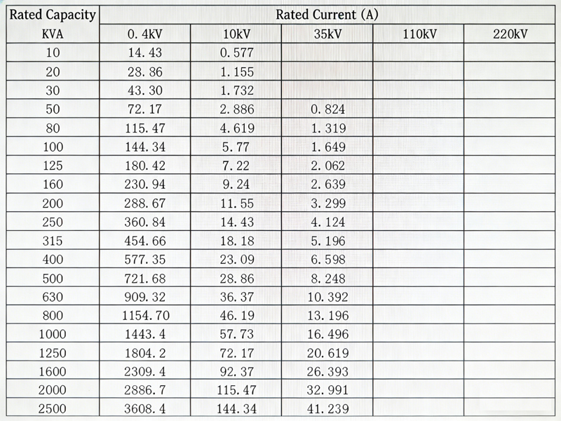
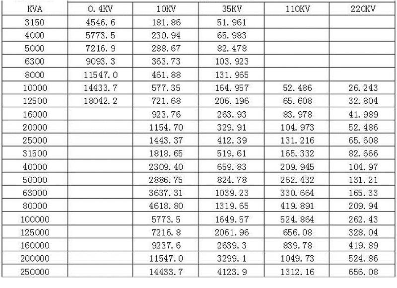
Distribution transformer output power meter
|
Rated Capacity kVA
|
Rated Current(A) | Output power when power factor is 1(KW) |
Output power when power factor is 0.9(KW) |
|
| High Volt 10kV | Low Volt 0.4kV | |||
| 50 | 2.886 | 72.17 | 47.63 | 42.86 |
| 80 | 4.619 | 115.47 | 76.2 | 68.58 |
| 100 | 5.77 | 144.34 | 95.26 | 85.73 |
| 125 | 7.22 | 180.42 | 119.07 | 107.16 |
| 160 | 9.24 | 230.94 | 152.42 | 137.17 |
| 200 | 11.55 | 288.67 | 190.52 | 171.47 |
| 250 | 14.43 | 360.84 | 238.15 | 214.33 |
| 315 | 18.18 | 454.66 | 300.07 | 270.06 |
| 400 | 23.09 | 577.35 | 381.05 | 342.95 |
| 500 | 28.86 | 721.68 | 476.3 | 428.67 |
| 630 | 36.37 | 909.32 | 600.15 | 540.13 |
| 800 | 46.19 | 1154.7 | 762.1 | 685.9 |
| 1000 | 57.73 | 1443.4 | 952.6 | 857.34 |
| 1250 | 72.17 | 1804.2 | 1190.77 | 1071.7 |
| 1600 | 92.37 | 2309.4 | 1524.2 | 1387.98 |
| 2000 | 115.47 | 2886.7 | 1905.2 | 1741.68 |
| 2500 | 144.34 | 3608.4 | 2381.54 | 2143.4 |
FAQ: Why can’t transformers be operated under overload?
Overload operation refers to the transformer operating beyond the current value specified on its nameplate.
Overload is divided into two types: normal overload and accidental overload. The former refers to overload caused by increased electricity consumption under normal power supply conditions. This often leads to increased transformer temperature, accelerated insulation aging, and reduced lifespan; therefore, overload operation is not permitted.
Under special circumstances, short-term overload operation of the transformer should not exceed 30% of the rated load (in winter) and 15% in summer.
For the latter, the accidental overload and permissible overload time requirements are shown in the table below: Permissible Overload
Transformers can operate under either normal overload or accidental overload conditions. Normal overload can be used frequently, and its permissible value is determined based on the transformer’s load curve, cooling conditions, and the load the transformer carried before the overload. Accidental overload (pcs) is permitted under accident conditions (for transformers that can still operate).
The permissible value for accidental overload should comply with the manufacturer’s specifications; if there are no manufacturer’s specifications, for self-cooled oil-immersed transformers, the requirements in the table below can be followed.
FAQ: Why are transformer ratings in kVA instead of kW?
Transformer ratings are always in kVA, not kW. As the name suggests, a transformer simply transfers power from one circuit to another without changing the power or frequency values. In other words, it can only increase or decrease the current and voltage values while keeping the power and frequency constant. General data is printed on the transformer nameplate for more detailed information,
such as VA rating, single-phase/three-phase (power or distribution transformer), step-up/step-down, connections, etc. Simply put, transformers have two types of losses:
- Copper loss
- Iron loss or insulation loss
Copper loss (I²R) depends on the current flowing through the transformer windings, while iron loss or core loss or insulation loss depends on the voltage. That is, the total loss depends on the voltage (V) and current (I) expressed in volt-amperes (VA), not on the load power factor (PF). This is why transformer ratings may be expressed in VA or kVA, not W or kW.
Let’s explain in more detail why transformer ratings are in VA instead of kW.
When manufacturers design transformers, they don’t know what kind of load the transformer will be connected to; for example, they are unsure of the exact application of the transformer in different scenarios. Loads can be resistive (R), inductive (L), capacitive (C), or mixed loads (R, L, and C). This means that there will be different power factors (PF) on the secondary (load) side of different types of connected loads, which also depends on R, L, and C. Thus, transformer ratings are expressed in volt-amperes (VA) rather than watts (W).
Let’s clarify the transformer rating in VA instead of W with a solved example. As long as the current/voltage magnitude is the same, the transformer losses remain constant, regardless of the power factor of the load current/voltage.
Example: Assume a single-phase step-up transformer with the following rating in kVA:
Primary voltage = 110V
Primary current = 100A
Secondary voltage = 220V
Secondary current = 50A
Secondary equivalent resistance = 5Ω
Iron loss = 30W
In the first case, if we connect a resistive load to the secondary of the transformer at unity power factor Φ = 1, then the total transformer loss is copper loss + iron loss, i.e., I²R + iron loss; the value is: (50² × 5) + 30W = 12.53kW
That is, the losses transmitted in the primary and secondary are still the same. (See also the example of secondary losses below)
The transformer output will be: P = V x I x Cos ϕ
Again, putting the secondary value in (if we put the primary value in the same value) P = 220 x 50 x 1 = 11kW. The transformer’s current rating is:
kVA = VVA ÷ 1000
kVA = (220 x 50) ÷ 1000 = 11 kVA.
Now, in the second case, a capacitive or inductive load is connected to the secondary winding of a transformer with a power factor Φ = 0.6. Again, the total transformer loss will be copper loss + iron loss, i.e.: I²R + iron loss; the value is: (50² x 5) + 30W = 12.53kW.
This proves that the primary and secondary losses are the same. However, the transformer output will be: P = V x I x Cos Φ
Putting in the secondary value again (if we put in the primary value, the value is the same), P = 220 x 50 x 0.6 = 6.6kW.
The transformer rating is: kVA = VA ÷ 1000
kVA = 220 x 50 ÷ (1000) = 11 kVA
This means that an 11kVA transformer rating means it can handle 11kVA. When it comes to converting 11kVA to 11kW (which we can achieve by increasing the power factor to 1 for a purely resistive load), it’s unpredictable, and even difficult to obtain different power factor values for inductive and capacitive loads.
It’s clear from the example above that transformers with the same rating (11kVA) but different output power (11kW and 6.6kW) have different power factor values due to the different power factor values after connecting different types of loads, which is unpredictable for transformer manufacturers. The loss is the same in both cases.
Therefore, these are the exact reasons why transformer ratings are in kVA rather than kW.
FAQ: Is the service life of a transformer 20 years?
The standard lifespan of a transformer is generally 20 years, as stipulated by national standards. Transformers are designed for a 20-year service life. However, in actual operation, most transformers often exceed this limit. For example, Article 88, Table 13 of the “Railway Power Management Regulations” specifies a transformer service life of 15 years.
Furthermore, the service life of a transformer can be affected by various factors, such as equipment quality, operating environment, maintenance frequency and condition, etc. Poor equipment quality, harsh operating environment, and improper maintenance can shorten the transformer’s lifespan. Therefore, to ensure the transformer’s service life, it is necessary to select reliable equipment, provide a good operating environment, and conduct regular maintenance and inspections.
Therefore, in practical use, an assessment and judgment should be made based on the specific conditions of the transformer, and corresponding measures should be taken to extend its service life.
The service life depends on the temperature rise limit of the insulation materials (oil and insulation materials).
When the transformer insulation operating temperature is 95℃, its service life is 20 years;
At 105℃, the service life is 7 years;
At 120℃, the service life is 2 years.
A cast-resin insulated dry-type transformer has a service life of 20 years at an operating temperature of 140℃; 7 years at 155℃; and 2 years at 177℃.
In practical applications, factors such as the actual operating conditions and efficiency of the equipment must also be considered. Nevertheless, most operating transformers exceed their expected 20-year service life. Furthermore, modern transformer structures have changed, adopting fully sealed structures that prevent direct contact between the transformer oil and air, which helps extend their lifespan, typically to 30 years. Therefore, under normal operation and maintenance, the actual lifespan of a transformer may exceed 20 years.
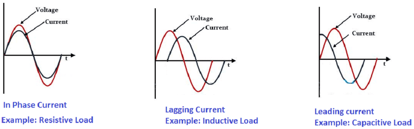
FAQ: What types of loads can a transformer handle?
Transformers can generally handle three types of loads: resistive loads, inductive loads, and capacitive loads. 1. Resistive Loads: When there is no phase difference between the load current and voltage and the power supply, the load is resistive (e.g., incandescent lamps, electric furnaces, etc.). Simply put, a purely resistive load that operates solely through resistive components is called a resistive load.
What is an inductive load? An inductive load generally refers to a load with inductive parameters. More precisely, it’s a load where the load current lags the load voltage by a phase difference. Examples include transformers, electric motors, electric fans, induction cookers, and air conditioners.
What is a capacitive load? A capacitive load generally refers to a load with capacitive parameters. The load current leads the voltage. A purely inductive load is one where the voltage phase leads the current phase by 90 degrees. Common capacitive loads include switching power supplies such as those used in computers and televisions.
FAQ: Why does UHV transmission use DC power?
UHV power transmission uses both DC and AC power. A notable difference is that longer lines often utilize DC transmission. Why? Because DC is better suited for long-distance storage, and its transmission cost is lower at the same voltage.
How come it’s now considered suitable for long-distance transmission? In Edison’s time, DC voltage couldn’t be changed, so its transmission distance was naturally shorter than AC’s. However, if the DC voltage were the same as AC, DC’s transmission advantages would immediately become apparent.
Firstly, AC power transmission occurs on the surface of the conductor, wasting the middle section.
DC, on the other hand, can be transmitted using only two conductors, allowing for thinner conductors. Secondly, DC requires only two conductors, while three-wire AC requires three, saving significant construction costs and land resources. Another factor is that DC is much simpler to expand than AC. AC, due to frequency and line position issues, requires multiple power plants to maintain consistent voltage, frequency, and phase if they need to be connected in parallel.
DC, however, only requires consistent voltage across all power plants. It’s like a porter moving goods from point A to point B. So, can DC completely replace AC? Absolutely not. First, DC voltage cannot be directly changed; it needs to be converted to AC and then transformed. Converting the voltage back to DC requires two additional devices: a rectifier to convert AC to DC and an inverter to convert DC back to AC.
From an investment perspective, the rectification and transformation alone account for more than half of the total investment in UHVDC. The low cost of UHVDC lies in its transmission process, making it more suitable for point-to-point long-distance transmission. Based on the information above, can you identify where the investment opportunities lie in ultra-high voltage power transmission?
FAQ: Why does high-voltage direct current (HVDC) transmission require two transmission lines?
HVDC transmission projects are divided into monopolar systems (either positive or negative) and bipolar systems (both positive and negative poles).
Monopolar HVDC overhead lines typically use negative polarity, i.e., the positive pole is grounded. This is because the corona electromagnetic interference and audible noise of the positive pole conductor are greater than those of the negative pole conductor; also, since lightning is mostly negative polarity, the probability of lightning flashover on the positive pole conductor is higher than that on the negative pole conductor.
Monopolar systems are less reliable and less flexible than bipolar systems. In practical engineering, bipolar systems are mostly used.
A bipolar system consists of two independently operating monopolar systems, facilitating phased construction of the project. Furthermore, during operation, if one pole fails and stops, it can automatically switch back to monopolar operation.