


Detailed Introduction to Substation Equipment and Their Working Principles
A substation functions like the “hub” and “transformer” of the power system. On one hand, it uses transformers to step up the voltage of electricity generated by power plants, enabling long-distance, low-loss transmission. On the other hand, near cities or industrial areas, it steps down the voltage to distribute electricity to households and factories. To accomplish this complex and critical task, substations are equipped with various types of equipment, each serving a distinct purpose.
In simple terms, this equipment can be divided into two main categories: primary equipment and secondary equipment. Primary equipment refers to the main devices directly responsible for the transmission and transformation of electrical energy, serving as the “body” of the substation. Secondary equipment, on the other hand, refers to the auxiliary devices used to monitor, measure, protect, and control the primary equipment, acting as the “brain” and “nervous system” of the substation.
Part 1: Primary Equipment
Definition: Primary equipment refers to the devices directly involved in the production, transformation, transmission, distribution, and utilization of electrical energy. They form the backbone of the substation and withstand high voltage and large current.
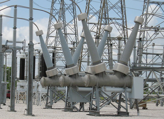
1. Power Transformer
![]()
-
Working Principle: Based on the principle of electromagnetic induction. When AC flows through the primary winding, it creates an alternating magnetic flux in the core, which induces an electromotive force (voltage) in the secondary winding. By changing the turns ratio between the primary and secondary windings, the voltage can be stepped up or down.
-
Key Point: It is the core of the substation but is a static device, operating solely via electromagnetic fields.
2. Switching Devices
-
Circuit Breaker:
-
Working Principle: The core function is arc quenching. When contacts separate to interrupt current, a high-temperature arc is generated. The circuit breaker uses a special medium (like vacuum, SF6 gas, or high-pressure air) to rapidly stretch, cool, and extinguish the arc within milliseconds, successfully interrupting the current.
-
-
Disconnecting Switch (Isolator) :
-
Working Principle: Relatively simple in construction, its main purpose is to provide a visible air-insulated break. It lacks a dedicated arc-quenching device, so it cannot be operated under load. It is only switched when no current flows, ensuring safety during maintenance.
-
-
Load Switch:
-
Working Principle: Falls between the two. It has some arc-quenching capability, allowing it to interrupt normal load currents, but it cannot interrupt short-circuit currents.
-
3. Current Limiting and Protection Devices
-
Fuse:
-
Working Principle: Utilizes the thermal effect of current. When the current exceeds a specified value for a certain duration, the fuse element (usually a low-melting-point metal wire or strip) melts due to the heat generated, thus opening the circuit and protecting downstream equipment.
-
4. Current Carrying Conductors and Insulators
-
Busbar:
-
Working Principle: Acts as a physical node. All incoming and outgoing electrical energy is collected and distributed here. It does not alter the current but provides a low-impedance conductor platform for connections.
-
-
Power Cable:
-
Working Principle: Transmits electrical energy through its inner conductor, using the outer insulation and protective layers to prevent energy leakage and external damage.
-
-
Insulator:
-
Working Principle: Relies on its special insulating material (like porcelain, glass, or polymer) and shape (e.g., sheds) to increase the creepage distance, support live conductors, and insulate them from ground or other live parts.
-
5. Reactive Power Compensation and Limiting Devices
-
Reactor:
-
Working Principle: Utilizes the property of inductance. When current flows through it, it generates an electromotive force that opposes changes in current. During a short circuit, it effectively limits the rate of rise and the magnitude of the short-circuit current.
-
-
Capacitor:
-
Working Principle: Utilizes the property of capacitance. In an AC circuit, the current through a capacitor leads the voltage. This characteristic can offset the lagging effect caused by inductive loads (like motors, transformers), thereby improving the power factor and reducing energy losses.
-
Part 2: Secondary Equipment
Definition: Secondary equipment refers to devices used for monitoring, measuring, controlling, protecting, and regulating the operating status of primary equipment. They operate at lower voltages and currents but involve complex logic and require high precision.
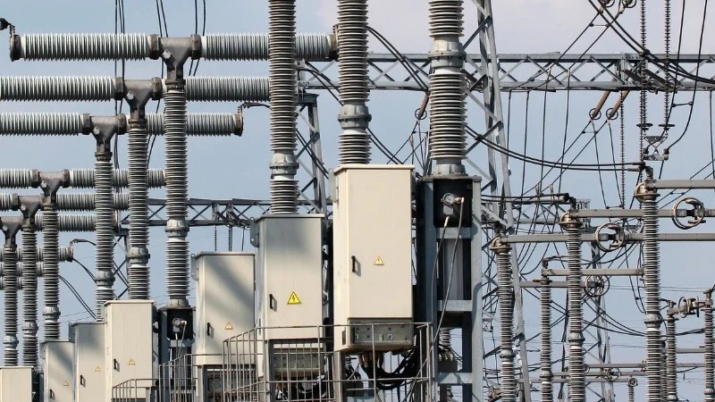
1. Instrument Transformers
![]()
-
Voltage Transformer:
-
Working Principle: Essentially a small transformer. It is always connected in parallel with the high-voltage line, stepping down the high voltage proportionally (e.g., 110kV / 100V) to provide a standard low-voltage signal for meters and protection devices.
-
-
Current Transformer:
-
Working Principle: Essentially a “step-down” transformer for current. It is connected in series with the high-voltage line, transforming the large current proportionally (e.g., 1000A / 5A) into a small current.
-
Special Note: Although they directly contact high voltage, their output consists of low-voltage, small-current signals, hence they are classified as secondary equipment. They act as the “bridge” between the primary and secondary systems.
-
2. Protection and Automation Devices
-
Protective Relay Device:
-
Working Principle: Continuously collects voltage and current signals from instrument transformers. When the detected signals (e.g., a sharp rise in current, sudden drop in voltage) match pre-set fault characteristics, it instantly (microseconds to milliseconds) issues a trip command to the circuit breaker to open and clear the fault. Common principles include differential protection, overcurrent protection, distance protection, etc.
-
-
Automatic Reclosing Device:
-
Working Principle: After the protective relay trips the breaker, this device waits for a very short, preset time (e.g., 0.5 seconds) and then automatically sends a close command, attempting to restore power. This is useful because many faults on overhead lines (like lightning strikes, wind-blown objects) are temporary, and reclosing can successfully restore supply.
-
3. Monitoring and Measurement Devices
-
Measuring Instruments:
-
Working Principle: Convert the secondary signals (e.g., 0-100V, 0-5A) from instrument transformers via internal circuits into pointer deflections or digital displays, providing visual readings of parameters like voltage, current, power, and energy.
-
-
Supervisory Control and Data Acquisition (SCADA) / Monitoring System:
-
Working Principle: Through a communication network, it collects data from across the station, such as circuit breaker status, disconnector positions, measurements, and protection actions. It uploads this information to computer screens in the control room and receives remote control commands (like “close,” “open”) from operators.
-
4. Control and DC Power Supply
-
DC Power Supply System:
-
Working Principle: Composed of a battery bank and a battery charger. Under normal conditions, AC power is rectified by the charger into DC power to float-charge the batteries and supply the loads. When AC power is lost (station blackout), the battery bank automatically and seamlessly takes over, supplying uninterrupted DC power to critical equipment like control systems, protection devices, and communication systems, ensuring reliable tripping during faults.
-
-
Automatic Devices:
-
Working Principle: Operate based on preset logic. For example, an Automatic Transfer Switch (ATS) / Auto-throw-in Equipment for Standby Power Supply, upon detecting the loss of the primary power source, automatically and quickly switches to the backup source. An Automatic Voltage Control (AVC) device automatically switches capacitors or adjusts transformer taps based on bus voltage levels to maintain voltage stability.
-
conclusion
| Equipment Category | Main Equipment | Core Function |
|---|---|---|
| Primary Equipment | Power Transformer | Changes voltage levels (e.g., step-up or step-down); the most core equipment of a substation. |
| Switching Devices (Circuit Breaker, Disconnect Switch/Isolator, Load Switch, Fuse, etc.) | Responsible for connecting or disconnecting circuits. Circuit breakers interrupt fault currents; disconnect switches are mainly used to create a visible disconnection point for maintenance. | |
| Instrument Transformers (Current Transformer, Voltage/Potential Transformer) | Converts high voltage and large current on the primary side to low voltage and small current usable by secondary equipment according to a ratio, while providing isolation. | |
| Busbar | A common conductive platform for collecting and distributing electrical energy, connecting all lines within the station. | |
| Lightning Protection Devices (Lightning Rod, Lightning Arrester) | Protects equipment in the station from damage caused by lightning overvoltage and switching overvoltage. | |
| Reactive Power Compensation Devices (Capacitor, Reactor) | Compensates for reactive power, improves power quality, and stabilizes system voltage. | |
| Secondary Equipment | Protective Relaying Devices | Monitors the status of primary equipment in real-time. In case of a fault, it quickly sends a signal or commands the circuit breaker to trip and clear the fault. |
| Measurement and Control Devices, Measuring Instruments | Measures and displays operating parameters (e.g., voltage, current, power), and can transmit signals remotely to a control center. | |
| Automation Systems, Communication Equipment | Implements substation automation and remote control, including data acquisition, monitoring (i.e., SCADA system), and communication with the dispatch center. | |
| DC Power Supply System | Provides stable and reliable DC power for secondary equipment (such as relay protection and control circuits), ensuring operation even during a main power outage. |
-
Primary Equipment are the Actors: Responsible for the transmission and transformation of electrical energy.
-
Secondary Equipment are the Decision-makers and Supervisors: Responsible for sensing, judging, and commanding what the primary equipment should do, and correcting it when errors occur.